
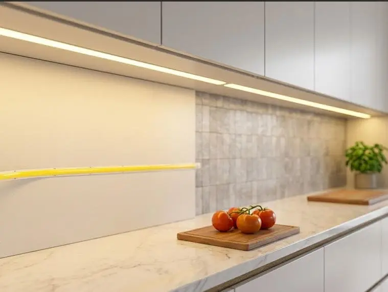
LED chip density per meter confuses many buyers who visit our production line. They see two COB strips that look identical, then discover one costs 30% more. Why? Density. Choose wrong, and you either overpay for smoothness you cannot see, or your project shows ugly light spots up close. I have watched contractors reorder entire batches over this single spec. Understanding density solves the problem before it reaches your job site.
LED chip density per meter primarily determines a COB strip's light uniformity and dot-free appearance, not its brightness. Higher density (480–840 chips/m) delivers seamless illumination but raises heat, power draw, and cost. Brightness depends on drive power, chip efficiency, and thermal design working together with density.
Let me break this down section by section. We will cover brightness, heat, color consistency, and cost. Each one connects back to density in a different way.
How do I choose the right chip density for my project's brightness needs?
Last year, a lighting designer from Melbourne asked us for the "brightest possible" COB strip. His real need turned out to be uniformity in shallow coves, not raw luminous flux.
Match density to viewing distance and diffuser depth, not brightness alone. Choose 320 chips/m for concealed coves, 480 chips/m for close-range cabinets and shallow channels, and 528+ chips/m for exposed, dot-free illumination. Brightness comes from wattage and chip quality, not chip count.
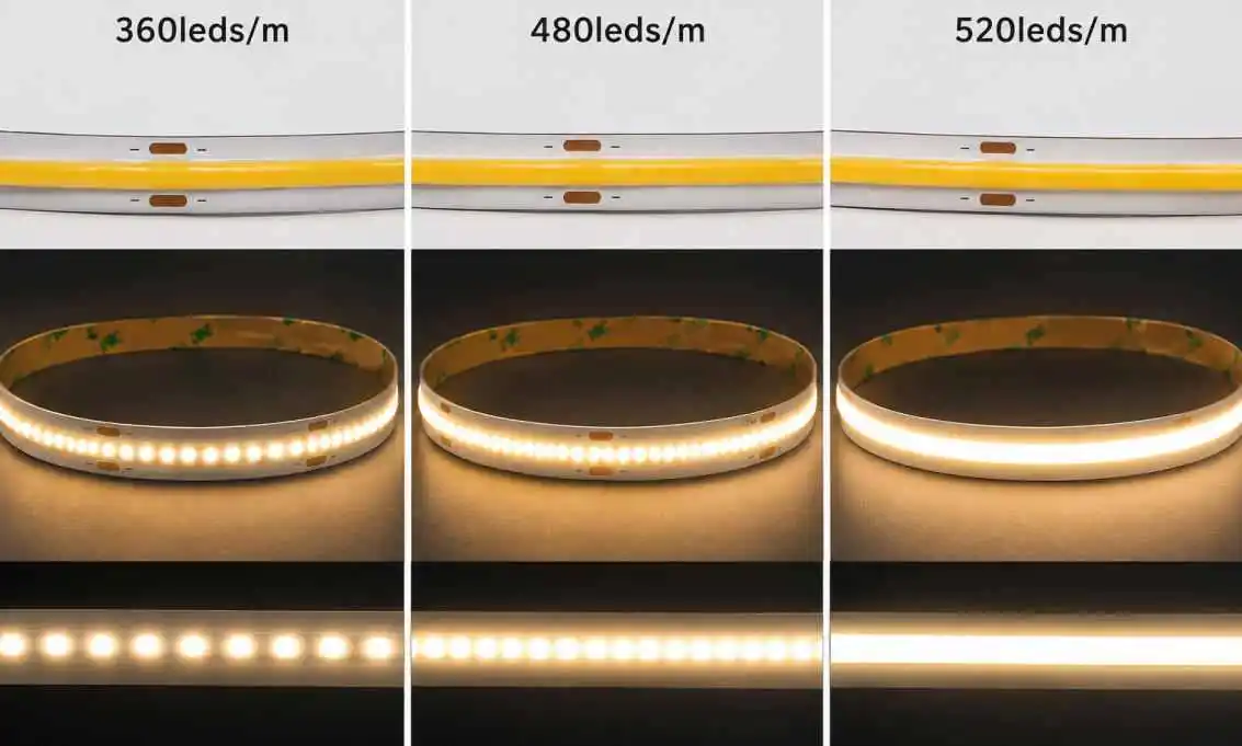
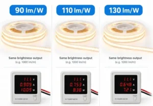
Density and brightness are related, but they are not the same thing. This is the mistake I see most often. A 480 chips/m strip is not automatically brighter than a 384 chips/m strip. One useful data point: a 384 chips/m COB strip typically delivers around 900–1,400 lm/m, while a 480 chips/m version reaches roughly 1,200–1,600 lm/m. But the gain comes from total drive power and chip quality, not the chip count by itself. I have tested 528 chips/m strips that output only 700 lm/m because each chip was driven gently.
A quick density selection table
| Chip Density | Typical Use Case | Viewing Distance | Luminous Flux Range |
|---|---|---|---|
| 320 chips/m | Hidden coves, indirect ceiling lines | 1m+ | 700–1,100 lm/m |
| 384–480 chips/m | Under-cabinet, shelf lighting, light channels | 0.3–1m | 900–1,600 lm/m |
| 528–840 chips/m | Exposed linear runs, retail displays, close-up detail | Under 0.3m | Varies with wattage |
What actually drives brightness
Three factors matter more than density: drive current per chip, chip efficacy 1, and how well the PCB sheds heat. When we spec a strip for a German distributor, we look at power consumption per meter first, then confirm the density supports the visual requirement. In my experience, chip count is not "the more the better." It just needs to be enough. What truly decides the result is whether density, wattage, and thermal design are matched properly — not any single number on a datasheet.
Also check the minimum cutting length. Higher-density strips often allow shorter cut intervals, which helps precise installations in millwork and joinery.
What impact does chip density have on heat management and long-term reliability?
The trade-off I weigh most often in sample development is this: pack in more chips for smoothness, or leave thermal headroom for lifespan. You rarely get both cheaply.
Higher chip density concentrates heat along the strip, making thermal dissipation harder. Above roughly 15W/m, tightly packed COB chips need aluminum profiles or heat sinks to prevent lumen decay and phosphor degradation. Reliability depends on matching density, wattage, and PCB design together.
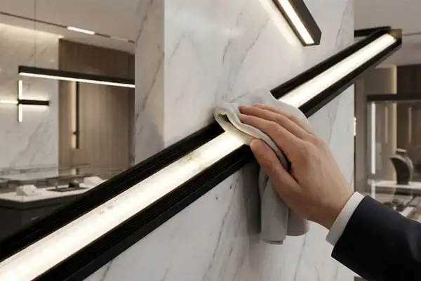
Heat is the silent killer of LED strips. When chips sit closer together, each one heats its neighbors. The industry guideline we follow is simple: once power exceeds about 15 W/m, heat dissipation becomes significantly harder because the chips are so tightly packed. At that point, surface mounting on wood or drywall is no longer safe for lifespan. You need an aluminum channel.
How heat damages high-density strips
Excessive junction temperature causes three problems. First, lumen decay 2 accelerates, so the strip dims early. Second, thermal quenching of the phosphor layer 3 shifts the light toward cooler color temperatures over time. Third, adhesive and solder joints fatigue faster. For long-run projects we ship to Australia, we specify heavier PCB copper thickness — usually 2oz or more — because the copper itself acts as the first heat spreader before any external profile.
Heat sink requirements by power level
| Power per Meter | Density Range (Typical) | Heat Sink Requirements |
|---|---|---|
| Under 10 W/m | 320–384 chips/m | Optional; flat surface mounting acceptable |
| 10–15 W/m | 384–528 chips/m | Aluminum profile strongly recommended |
| Over 15 W/m | 528+ chips/m | Aluminum profile mandatory; consider deeper channels |
One more reliability angle: higher power per meter worsens voltage drop on long runs. That is why we push 24V or 48V DC systems and planned power injection points for runs beyond 5 meters. A high-density strip with poor injection planning will look dimmer and warmer at the far end — the exact opposite of the uniformity you paid for.
Will higher chip density guarantee better color consistency in my COB strips?
A QC lesson shaped my view here. We once compared two production batches under a light booth — same 512 chips/m density, visibly different whites. Density had nothing to do with it.
No. Chip density does not guarantee color consistency; LED binning control does. Higher density actually makes binning variations more visible, because the eye reads a COB strip as one continuous light surface. Demand tight MacAdam ellipse tolerances (3-step or better) regardless of density.
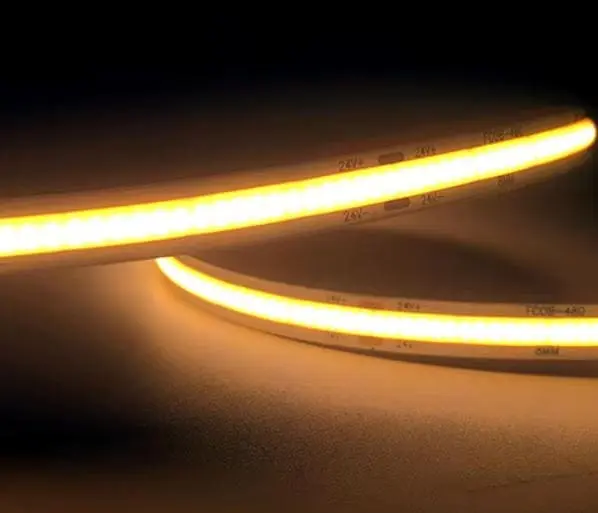
This is the most misunderstood point in the whole density conversation. Buyers assume that a premium chip count implies premium color control. In reality, the two specs come from different parts of the supply chain. Color consistency comes from chip binning 4, phosphor mixing, and batch management. Density only changes how visible the flaws are.
Why density amplifies color flaws
On a standard SMD strip, individual dots hide small tint differences. On a dense COB strip, the phosphor layer creates dot-free illumination — one unbroken surface of light. Your eye becomes ruthless. A slight green or pink shift between sections that would vanish among discrete dots now shows as a visible tint band. This heightened sensitivity to MacAdam ellipse variations is exactly why we hold our project-grade strips to strict binning before every export shipment to Germany, where architectural specifiers check color tolerance in their tenders.
What to verify instead of density
- Binning tolerance: ask for 3-step MacAdam or tighter for exposed installations.
- Batch matching: order full project quantities from one production batch when possible.
- Color rendering index: COB's continuous phosphor layer supports high CRI and strong R9 values without the rainbow effect of multi-chip SMD strips — but only if the phosphor recipe is controlled.
- Beam angle consistency: uneven phosphor application causes angle-dependent tint shifts; check the strip from oblique angles, not just straight on.
Batch-to-batch variance is one of the most common complaints we hear from renovation contractors. My advice is blunt: specify color tolerance in writing, and treat density as a separate line item entirely.
How does chip density influence pricing and cost-efficiency for bulk orders?
When distributors request quotes from our team, the density line on the spec sheet moves the price faster than almost any other single variable except CRI grade.
Higher chip density raises COB strip cost by roughly 20–40% versus comparable lower-density or SMD options, driven by chip count, heavier copper PCBs, and tighter QC. Cost-efficiency peaks at mid-density (384–480 chips/m) for most projects; ultra-high density pays off only in exposed, close-view applications.
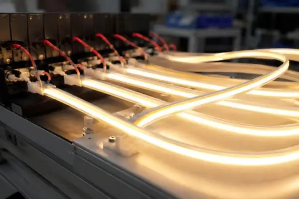
Let me be transparent about where the money goes. Chips are the obvious cost, but they are not the whole story. Higher density often requires greater PCB copper thickness for heat spreading, more phosphor material, stricter binning, and slower placement on the line. Each factor compounds in bulk pricing. In B2B contexts, COB commonly carries a 20–40% premium over SMD alternatives, even in cases where SMD wins on raw efficacy.
Where high density saves money
It is not all extra cost. Dense COB strips can eliminate expenses elsewhere:
| Cost Factor | Low-Density COB (320/m) | High-Density COB (528+/m) |
|---|---|---|
| Strip unit price | Lower | 20–40% higher |
| Diffuser requirement | Deep opal diffuser needed | Shallow or clear diffuser works |
| Channel depth | Deeper profile for mixing distance | Slim profiles acceptable |
| Power supply sizing | Smaller PSU | Larger PSU, more injection points |
| Rework risk from visible dots | Higher in exposed installs | Near zero |
For a wholesaler stocking general-purpose product, mid-density is the commercial sweet spot. For a design firm specifying exposed linear details in retail or hospitality, the high-density premium is cheaper than a callback. One of our long-term Australian partners standardized on two SKUs — 384 and 528 chips/m — instead of five, which simplified his inventory and improved his per-reel pricing through volume consolidation. That kind of SKU discipline usually beats chasing the highest number on the datasheet. Also remember downstream costs: higher power consumption per meter means bigger drivers and heavier wiring across a bulk project, and those line items add up quietly.
Conclusion
Chip density shapes uniformity first, brightness second. Match density to viewing distance, control heat above 15W/m, demand tight binning, and buy the density your project needs — nothing more.
Footnotes
- Explains the relationship between chip efficacy and total light output in LED systems. ↩︎
- Authoritative government resource explaining the causes of lumen decay and thermal management in LEDs. ↩︎
- Scientific overview of phosphor layers and their thermal sensitivity in LED applications. ↩︎
- Defines the industry standard for color consistency and binning using MacAdam ellipses. ↩︎


 English
 Spanish
 German
 Russian
 Arabic
 French
 Portuguese