
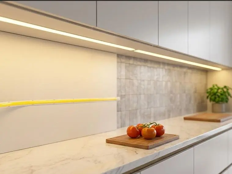
Buyers often ask us about COB LED strip beam angle. Spec sheets contradict each other, projects get quoted wrong, and installers blame the strip when the real problem sits elsewhere.
Most COB LED strip lights have a typical beam angle of about 180°. This wide spread comes from the continuous phosphor coating layer over dense chips. Some narrower COB variants exist at 120° to 145°, but 180° is the standard native specification.
That is the short answer. But the number on the datasheet is only half the story. Let me walk you through what actually matters when you plan a project.
How does beam angle affect uniformity and glare in my COB strip installations?
A German contractor once sent our team photos of two identical coves. One looked flawless. The other showed a harsh hotline on the ceiling. Same strip, same batch — different mounting.
A 180° beam angle spreads light evenly across surfaces, which reduces hotspots and delivers the seamless, dot-free look COB strips are known for. However, wide angle illumination also raises glare risk if the strip is mounted within the direct line of sight.
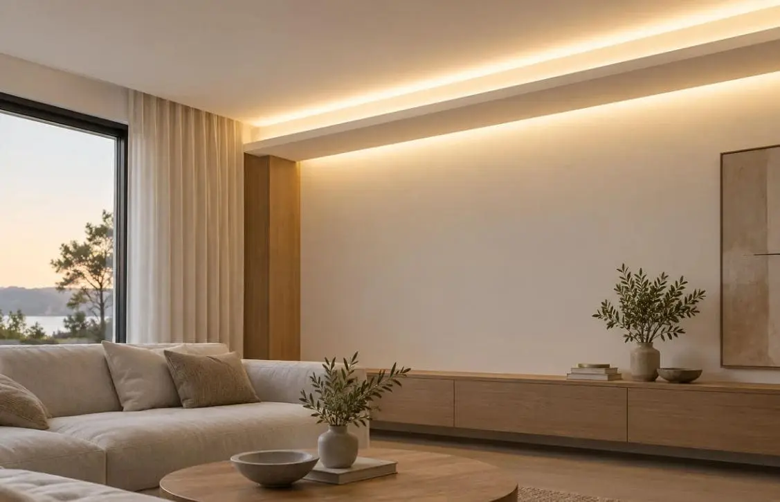
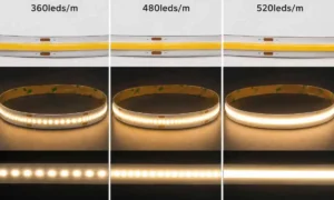
Beam angle describes the light distribution pattern of a source — the spread, measured in degrees, within which most of the luminous flux 1 travels. COB strips sit at the wide end of the common 30°–180° range discussed for LED strips. The technical foundation is chip density. Many COB strips carry more than 480 LEDs per meter under a continuous phosphor coating layer 2. That coating acts as the primary optic. It scatters light along the entire strip, so you get spotless linear lighting even without an external diffuser.
Now compare that with a standard SMD strip. In the SMD vs COB comparison, SMD strips typically emit at about 120° from discrete points. Those points create visible dots and scalloping unless you add a diffuser and mounting depth. COB is broader and smoother by default.
Uniformity versus glare: the trade-off
Wide spread is a gift for uniformity but a risk for glare. Here is how I frame it for clients:
| Factor | 180° COB strip | 120° SMD strip |
|---|---|---|
| Light distribution pattern | Continuous, wide wash | Discrete points, narrower cone |
| Hotspot risk | Very low | Moderate to high |
| Glare if visible to the eye | Higher (light spills sideways) | Lower (more directional) |
| Diffuser dependency | Optional for smoothness | Usually required |
| Shallow channel performance | Excellent | Poor |
One more nuance worth knowing: high-reflectivity white solder masks on the flexible PCB substrate 3 reclaim stray light and reinforce intensity at the extreme 180° "wings." That is great for wash effects, but it also means edge spill you must plan for. If viewers can see the strip directly, recess it, shield it, or use an aluminum profile housing with a frosted cover. In our experience, glare complaints almost never trace back to the beam angle itself — they trace back to sightlines.
Can I customize beam angle for specific project or architectural requirements?
When we co-develop private-label strips with distributors in Australia, beam angle customization comes up in almost every ODM brief. The honest answer surprises some buyers.
Yes, beam angle can be adjusted, but rarely by changing the strip itself. Narrower COB variants at 120° or 145° exist, and secondary optics, lens covers, and aluminum profile housing shape the effective spread far more flexibly than custom chip-level engineering.
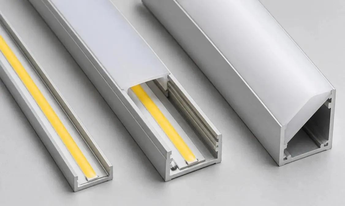
Here is the key distinction I always draw for specifiers. There are two beam angles in every project: the native emission angle of the strip, and the effective beam spread once installed. The native angle is set at production. The effective spread is set by everything around the strip. That distinction explains why some sources describe COB strips as 180° while other product pages advertise 120° or 145° — the narrower listings are usually purpose-built variants for directional output with less spill.
Ways to control the installed beam
- Choose a narrower COB variant. Products rated 120°, 140°, or 145° are built for concentrated output, such as wall grazing or task zones.
- Add secondary optics. Lensed profile covers can narrow the spread to focused cones — useful for grazing textured stone or highlighting joinery.
- Specify the profile geometry. A deep aluminum profile housing with a recessed strip naturally cuts the side wings and tightens the output.
- Angle the mounting. A 45° corner profile redirects the whole light distribution pattern toward the target surface.
There is also an emerging factory-level option: micro-prismatic surface texturing on the phosphor layer. It reduces total internal reflection 4 and maximizes wide-angle lumen delivery. Refractive index tuning of the silicone-phosphor matrix similarly optimizes the photon exit angle at the air-encapsulant interface. These are chip-level refinements we track closely, but for most projects they are not the lever you should pull. For low-MOQ custom runs, pairing a standard 180° strip with the right profile and optic is faster, cheaper, and easier to reproduce batch after batch. That is the route we recommend in nine out of ten briefs.
Which beam angle should I choose for wall washing versus task lighting applications?
A lighting designer in Melbourne once specified a 145° strip for a cove because the number "felt more controlled." The mockup looked patchy. We swapped in a 180° strip and the wash smoothed out immediately.
Choose 180° COB strips for wall washing, coves, and ambient illumination, because the wide spread blends light seamlessly across surfaces. Choose narrower 120°–145° variants for task lighting, wall grazing, or anywhere you need directed output with minimal spill.
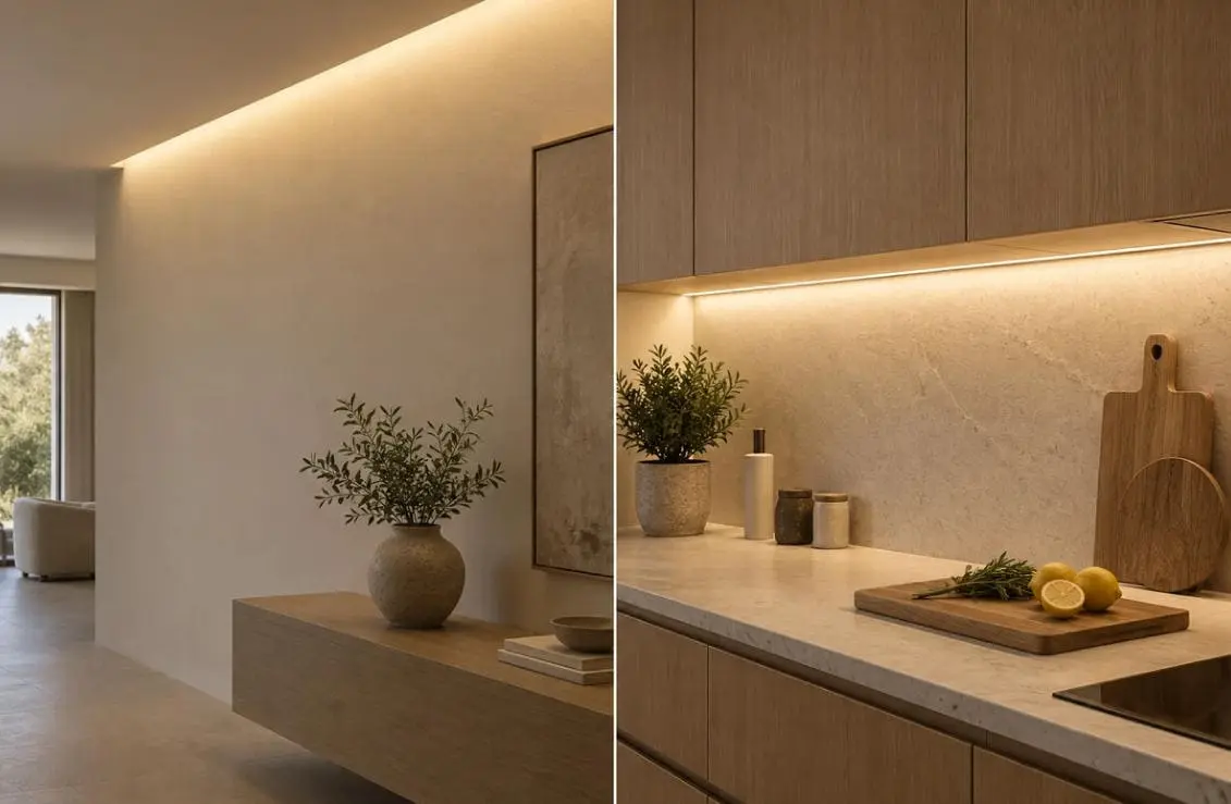
The logic is simple. Wall washing wants blend. Task lighting wants control. Match the spread to the job:
| Application | Recommended beam angle | Why it works |
|---|---|---|
| Wall washing / coves | 180° | Wide angle illumination blends across the wall with no striping |
| Under-cabinet ambient | 180° | Even countertop coverage from shallow channels |
| Task lighting (desks, benches) | 120°–145° | Concentrates luminous flux where hands work |
| Wall grazing (texture) | 120°–145° + optics | Tight angle exaggerates shadows on stone or brick |
| Backlighting panels | 180° | Fills the cavity evenly, avoids bright center lines |
| Shelf and display edges | 180° with diffuser | Dot-free effect at very close viewing distance |
Why shallow spaces favor COB
One point the ranking guides get right: COB strips are the industry-standard choice for shallow mounting depths. In a 10mm-deep channel, an SMD strip still shows dots because there is no room for light mixing. A 180° COB strip produces spotless linear lighting in that same space. For under-cabinet work, joinery reveals, and slim handrail profiles, this is decisive.
For task lighting, brightness on the work plane matters more than raw output. A narrower variant delivers more lux per watt onto the target. But do not forget the color rendering index. For kitchen benches and retail counters, we ship CRI 90+ strips regardless of beam angle, because accurate color under task light is what end clients actually notice.
Does beam angle impact color consistency and brightness across long-run installations?
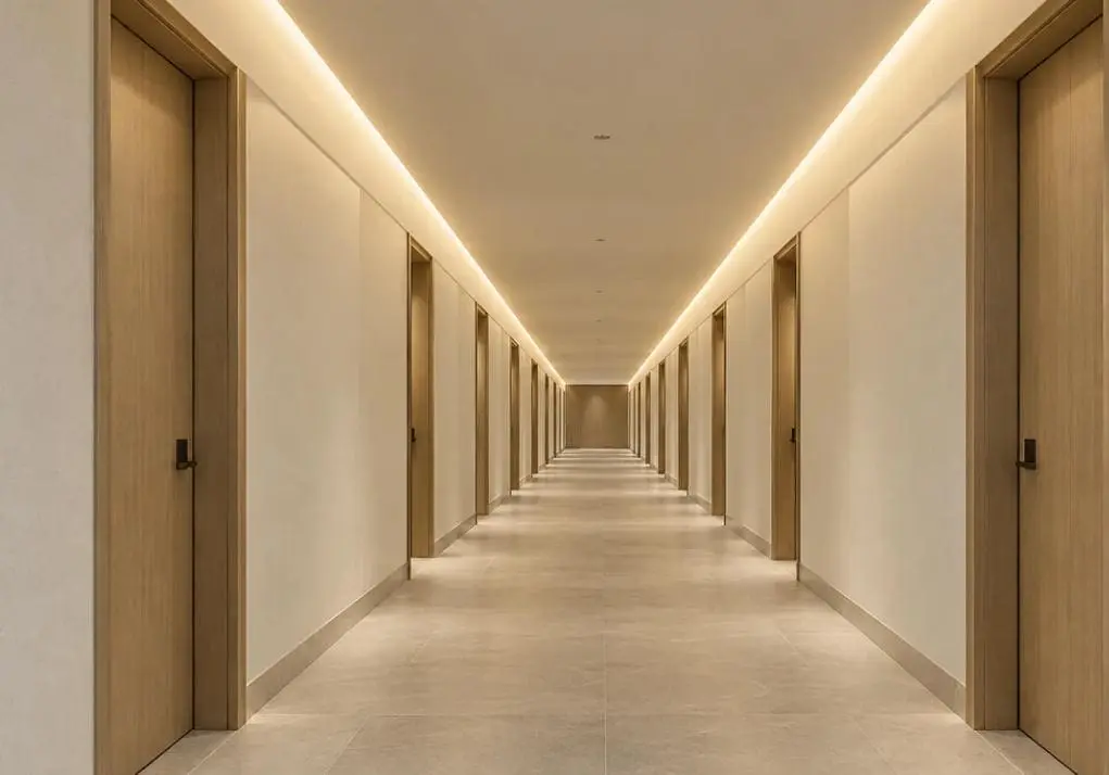
Long-run consistency is where our QC process earns its keep. When a wholesaler orders 2,000 meters for a hotel corridor, a 3-degree spec difference is not what keeps me up at night — batch variance is.
Beam angle itself has minimal impact on color consistency in long runs. Perceived shifts usually come from batch-to-batch phosphor variance, voltage drop, or thermal effects. Consistent binning, proper drivers, and good heat dissipation matter far more than the angle rating.
Let me be direct about something, because it shapes how I advise every client. Most COB strips sit around 180° because they are built for broad, uniform emission — not for focused output like a spotlight. And honestly, I think projects obsess over this number too much. A few degrees of difference is usually invisible to the naked eye. What genuinely changes the final result is the channel depth, the mounting position, and whether you use an aluminum profile at all. Get the installation wrong, and the effect degrades dramatically — no beam angle spec will save it.
That said, three real mechanisms can affect long-run appearance:
The three factors that actually shift long-run results
| Factor | What happens | How to control it |
|---|---|---|
| Voltage drop | Far end dims and can warm in tint | Use 24V or 48V high-voltage designs, feed power from both ends |
| Thermal load | Phosphor ribbon expansion can cause subtle thermal-induced beam shifting | Mount on aluminum profile housing for heat dissipation efficiency |
| Batch variance | Adjacent reels show visible color steps | Demand tight binning and single-batch supply per project |
Thermal-induced beam shifting is real but subtle: as the phosphor ribbon expands under high heat, the light distribution pattern can alter slightly. The fix is not a different beam angle — it is thermal management. A quality flexible PCB substrate bonded to an aluminum channel keeps junction temperatures stable, which protects both the beam shape and the color point over years of operation.
For our export projects to Germany and Australia, we hold each project order to a single production batch and verify color consistency reel by reel before shipping. Contractors doing 30-meter continuous runs care about invisible joints and uniform tint far more than whether the datasheet says 175° or 180°. That is the right priority.
Conclusion
Most COB LED strip lights emit at roughly 180°, with 120°–145° variants for directional needs. But installation method, profile choice, and batch consistency shape your final result far more than the angle number.
Footnotes
- Wikipedia entry defining the measure of the total perceived power of light. ↩︎
- U.S. Department of Energy resource explaining the fundamental technology and materials used in LED manufacturing. ↩︎
- Authoritative Wikipedia entry defining flexible printed circuits and their substrate materials. ↩︎
- Scientific explanation of light trapping within materials like LED phosphor layers. ↩︎

 English
 Spanish
 German
 Russian
 Arabic
 French
 Portuguese