
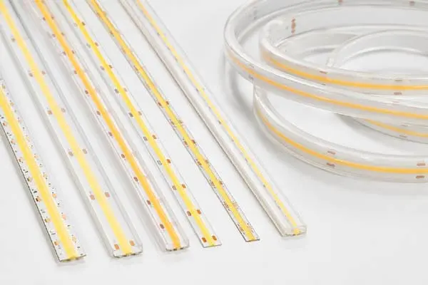
We ususally get calls from contractors who installed LED strips just two years ago—and already see noticeable dimming, color shifts, or dead segments creeping across their projects.
LED strip lights rarely burn out suddenly. Instead, they lose brightness gradually due to heat accumulation, unstable voltage, low-quality components, moisture ingress, and poor installation practices. These factors push LEDs beyond their designed operating conditions, accelerating lumen depreciation and shortening real-world lifespan far below manufacturer claims.
Understanding why LED strips fade early is the first step toward preventing it heat accumulation 1. Below, we break down the most critical causes—starting with the single biggest factor our production and field data consistently points to.
Why is my LED strip losing brightness faster due to poor thermal management?
On our production floor, we run thermal aging tests on every new strip design, and the results always confirm the same lesson: heat is the silent killer of LED brightness UV radiation 2.
Poor thermal management traps heat around LED chips, raising junction temperatures and accelerating phosphor degradation, solder fatigue, and encapsulant yellowing. This is the single most important factor behind premature lumen depreciation in LED strip lighting installations.
How Heat Damages LED Strips
LEDs are far more efficient than incandescent bulbs, but they are not heat-free. A typical LED converts roughly 30–40% of electrical energy into light. The rest becomes heat. In a single LED, that heat is manageable. But in a dense LED strip with 120 or even 240 LEDs per meter, thermal energy builds up fast.
When that heat has nowhere to go, the junction temperature of each LED chip rises. Higher junction temperatures 3 cause several problems at once. The phosphor layer—responsible for converting blue light into warm white—degrades faster. The silicone or epoxy encapsulant yellows and becomes less transparent. Solder joints weaken over time. Adhesive backing loses grip, which then causes partial detachment and even worse heat transfer.
Where Heat Gets Trapped
We have seen many installations where a high-quality strip fails early simply because it was mounted inside a sealed wooden cove or a narrow plastic channel with no ventilation. The strip itself was fine. The environment killed it.
Here are common heat-trapping scenarios:
| Installation Scenario | Thermal Risk Level | Why It Matters |
|---|---|---|
| Aluminum channel with open back | Low | Metal conducts heat away efficiently |
| Recessed ceiling slot, no channel | Medium-High | Drywall and wood insulate heat |
| Sealed plastic diffuser, no venting | High | Plastic traps heat, diffuser blocks airflow |
| Inside cabinet with doors closed | High | Enclosed air heats up with no escape path |
| Outdoor install in direct sun | Very High | Ambient temperature adds to strip's own heat |
Density and Drive Current Matter
Higher-density strips produce more heat per meter. A 240 LED/m strip puts out significantly more thermal energy than a 60 LED/m version, even if the per-LED power is similar. When we design custom strips for long architectural runs, we always discuss the thermal environment with the buyer before finalizing LED density. Pushing brightness up without planning for heat is a recipe for early decay.
The Practical Fix
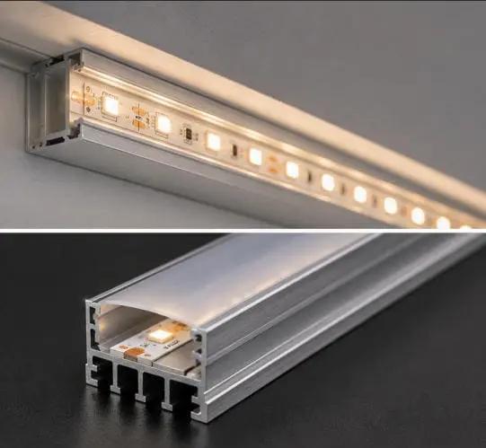
Mount strips on aluminum extrusions whenever possible. Even a thin aluminum channel can reduce junction temperature by 10–15°C compared to bare wood or plastic. In enclosed spaces, consider lower-density strips or add ventilation gaps. Always account for ambient temperature—an LED strip rated for 50,000 hours at 25°C ambient may only deliver 20,000 hours at 45°C ambient.
How do low-quality chips and thin PCBs shorten the lifespan of my project-grade strips?
When we source LED chips for our Glowin strips, our engineers evaluate die quality, phosphor consistency, and wire bonding reliability—because these hidden details determine whether a strip lasts five years or fifteen.
Low-quality LED chips suffer from unstable luminous output, faster phosphor aging, and weaker wire bonds. Combined with thin, low-copper-weight PCBs that conduct heat poorly and carry current unevenly, these components create strips that dim faster, shift color sooner, and develop dead spots far earlier than project specifications require.
Why Chip Quality Varies So Much
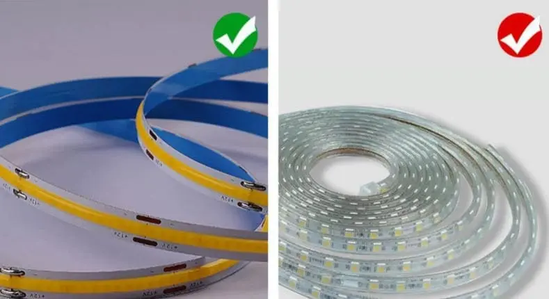
Not all LED chips are created equal. Top-tier chip manufacturers invest heavily in epitaxial growth precision, phosphor formulation, and binning consistency. Lower-tier suppliers cut corners on all three. The result is chips that may look identical on a datasheet but behave very differently over time.
A poorly grown LED die may have more crystal defects. These defects act as non-radiative recombination sites—places where electrical energy becomes heat instead of light. More internal heat means faster degradation from the inside out.
Phosphor quality is another hidden variable. The phosphor layer 4 in white LEDs converts blue light into broader-spectrum white light. Cheap phosphors break down faster under heat and UV exposure, causing noticeable color shift—often a gradual yellowing or a shift toward blue as the phosphor thins out.
PCB Thickness and Copper Weight
The printed circuit board 5 under the LEDs is not just a mounting surface. It is the primary electrical conductor and a critical part of the thermal path. Thin PCBs with low copper weight have two problems: they resist electrical current more (causing heat), and they transfer thermal energy less efficiently.
| PCB Specification | Typical Use | Effect on Lifespan |
|---|---|---|
| 1 oz copper, single layer | Budget consumer strips | Poor heat spread, higher trace resistance, faster decay |
| 2 oz copper, single layer | Mid-range project strips | Adequate for moderate density, good thermal transfer |
| 2 oz copper, double layer | High-end project strips | Better current distribution, lower hotspots, longer life |
| Aluminum-core PCB | Premium and high-power strips | Excellent thermal dissipation, longest lifespan potential |
Our experience shipping to contractors in Germany and Australia has taught us that buyers often compare strips by brightness and price. But the strips that hold up on five-year warranty claims are the ones built on heavier copper PCBs with well-binned chips.
Wire Bonding and Encapsulation
Inside each LED package, a tiny gold or copper wire connects the chip to the lead frame. Poor bonding—whether from contamination, incorrect pressure, or cheap materials—creates a weak point. Over thousands of hours of thermal cycling, weak bonds crack. That is when individual LEDs go dark.
Encapsulation also matters. The silicone or epoxy that covers the chip protects it from moisture, dust, and mechanical stress. Low-quality encapsulants yellow faster, absorb moisture, or peel away from the chip surface. Once the chip is exposed, degradation accelerates.
What Buyers Should Look For
Ask suppliers about chip brand, binning tolerance (especially for color temperature and forward voltage), PCB copper weight, and encapsulant material. These are the details that separate a strip that dims 20% in three years from one that dims 20% in ten.
What role does voltage instability play in the premature decay of my long-run LED installations?
We regularly consult with contractors who run 10-meter or even 20-meter continuous LED strips, and the most common complaint we help troubleshoot is uneven brightness—a problem almost always rooted in how power reaches the strip.
Voltage instability—from undersized power supplies, long uncompensated cable runs, noisy drivers, or incompatible dimmers—causes uneven current distribution, thermal hotspots, and excessive stress on LED chips. Over time, this accelerates lumen depreciation and creates visible brightness inconsistency across the installation.
Voltage Drop: The Long-Run Problem
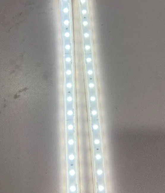
Every electrical conductor has resistance. The longer the run, the more voltage drops between the power supply and the far end of the strip. LEDs near the supply get full voltage and full brightness. LEDs at the far end receive less. This creates a visible gradient—bright near the feed point, dim at the end.
But the problem goes beyond aesthetics. When voltage drops, the driver or the strip's own circuitry may try to compensate by drawing more current at the feed point. That creates localized overheating and accelerates decay in the LEDs closest to the power injection.
How Power Supply Quality Affects Lifespan
A cheap, unregulated power supply introduces voltage ripple 6—small, rapid fluctuations in output voltage. LED chips experience these fluctuations as current spikes. Each spike generates a brief thermal pulse. Over millions of cycles, these micro-stresses degrade the chip, the phosphor, and the solder joints.
| Power Issue | Symptom | Long-Term Effect |
|---|---|---|
| Undersized power supply | Overheating, voltage sag | Accelerated component aging, potential fire risk |
| Voltage ripple / noise | Visible flicker, micro-stress | Phosphor degradation, solder fatigue |
| Incompatible dimmer | Flicker at low levels, buzzing | Driver stress, inconsistent LED current |
| Long cable run, no injection | Dim far end, bright near end | Uneven aging, early failure at feed point |
| Overloaded multi-strip setup | General dimming, heat buildup | Shortened lifespan across entire system |
Overdriving: Brighter Today, Darker Tomorrow
Some installations run LEDs at or above their maximum rated current to squeeze out extra brightness. This works in the short term. But overdriving raises junction temperature sharply, and the relationship between current and heat is not linear—it is exponential at the high end. A 20% increase in drive current 7 can reduce lifespan by 50% or more in some chip designs.
When we spec strips for a project, we recommend running them at 70–80% of maximum rated current. The brightness difference is barely noticeable, but the lifespan improvement is significant.
Practical Solutions for Voltage Stability
For long runs, inject power from both ends or at multiple mid-points. Use properly sized wire gauges. Choose constant-current drivers or well-regulated constant-voltage supplies with low ripple. Always verify dimmer compatibility before installation. And size your power supply at 70–80% load capacity—never 100%.
These steps cost a little more upfront but prevent callbacks, warranty claims, and disappointed clients down the line.
How can I prevent environmental factors from causing color shifts and light decay in my outdoor projects?
Our team has worked on outdoor specifications for hospitality and landscape projects in coastal Australia, and we have seen firsthand how salt air, UV exposure, and seasonal temperature swings can devastate even well-made LED strips within a few years if the installation ignores environmental realities.
Environmental factors—including humidity, salt spray, UV radiation, dust, chemical exposure, and thermal cycling—attack LED strip materials from the outside in. Choosing the correct IP rating, using sealed extrusions, specifying UV-stable materials, and planning for regular maintenance are essential steps to prevent premature color shift and light decay in outdoor and harsh-environment installations.
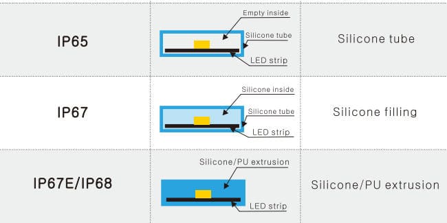
Moisture and Humidity
Water is one of the most destructive forces for electronics. Even in the absence of direct rain, high ambient humidity can cause condensation inside LED channels and enclosures. Over weeks and months, this moisture corrodes copper traces, degrades solder joints, and creates intermittent short circuits. The result is flickering, dead segments, and accelerated lumen loss.
Choosing the right IP rating 8 is essential. IP20 strips are fine for dry indoor spaces. But for bathrooms, kitchens, covered patios, or any space with elevated humidity, IP65 or higher is necessary. For submersion or direct water contact, IP67 or IP68 is required.
However, IP rating alone is not enough. The quality of the silicone coating or the potting compound matters. Cheap coatings can crack, peel, or absorb moisture over time—defeating the purpose of the rating. We always recommend that buyers ask for material certifications and UV-aging test results when specifying outdoor-grade strips.
UV Radiation and Material Degradation
Prolonged UV exposure degrades many of the polymers used in LED strip construction. Silicone coatings can yellow. Adhesive backings can weaken. In some products, the phosphor layer itself can be affected, causing gradual color shift toward blue as the phosphor thins.
For outdoor applications, specify strips with UV-stabilized encapsulants. Aluminum channels with UV-resistant diffuser covers add another layer of protection. Avoid using bare strips in direct sunlight without some form of shielding.
Salt Spray, Chemicals, and Dust
Coastal environments introduce salt-laden air that accelerates corrosion on exposed metal contacts and solder. Industrial kitchens expose strips to grease, steam, and cleaning chemicals. Dusty environments—warehouses, workshops, construction zones—coat strips with insulating layers that trap heat.
Each of these stressors demands a tailored approach:
- Coastal: Use IP67+ strips with marine-grade connectors and sealed extrusions.
- Commercial kitchens: Choose strips with chemical-resistant coatings and plan for regular cleaning access.
- Dusty environments: Use enclosed channels and schedule periodic cleaning to maintain thermal performance.
Thermal Cycling
Outdoor installations experience wide temperature swings between day and night, and between seasons. Each cycle causes materials to expand and contract slightly. Over thousands of cycles, this mechanical fatigue can crack solder joints, loosen wire bonds 9, and create micro-fractures in PCB traces. The result is intermittent failures that are difficult to diagnose.
Flexible, high-quality solder alloys and robust PCB designs handle thermal cycling better. When we design strips for export to climates with extreme temperature ranges, we test for thermal shock resistance as part of our quality control process.
Prevention Checklist for Outdoor Projects
- Match IP rating to the specific environment—do not just pick "waterproof."
- Specify UV-stable encapsulant and diffuser materials.
- Use sealed, marine-grade connectors for all junction points.
- Mount in aluminum channels for both thermal and physical protection.
- Plan for maintenance access—cleaning dust and checking seals.
- Verify that adhesive and potting materials resist the chemicals present in the space.
- Choose strips tested for thermal cycling if the installation faces wide temperature swings.
Conclusion
LED strip lifespan is a system outcome—not just a chip spec. Heat, power quality, component grade, environment, and installation all interact. Manage them together, and your project stays bright for years.
Footnotes
- Explains how heat accumulation directly impacts LED lifespan and performance. ↩︎
- Examines the failure modes and reliability of UV LEDs due to various factors, including UV exposure. ↩︎
- Replaced HTTP 404 link with an authoritative Wikipedia page explaining junction temperature in electronic devices, including LEDs. ↩︎
- Replaced HTTP 403 link with an authoritative Wikipedia page defining phosphor and its use in lighting. ↩︎
- Highlights the PCB's crucial role in thermal management and heat dissipation for LEDs. ↩︎
- Explains voltage ripple in power supplies and its impact on electronic component performance. ↩︎
- Illustrates how increasing drive current impacts LED operating temperature and longevity. ↩︎
- Replaced HTTP 403 link with an authoritative International Electrotechnical Commission (IEC) page explaining IP ratings. ↩︎
- Details bond wire failure mechanisms in power LED devices due to thermomechanical fatigue. ↩︎

 English
 Spanish
 German
 Russian
 Arabic
 French
 Portuguese