

Every year, our production team reviews field failure reports from contractors across Germany and Australia. The pattern is clear. Most LED strip failures in tough conditions trace back to three root causes: poor sealing, bad heat management, or unstable power delivery.
To keep LED strip lights running reliably in harsh environments, you must engineer the entire system—not just the strip. That means selecting the correct IP rating, managing heat with proper mounting and channels, stabilizing voltage across long runs, and enforcing strict quality control from your supplier. Each factor protects against a different failure mode.
This guide breaks down the four critical areas you need to get right. Whether you are installing strips on a coastal boardwalk, inside a freezer, or along a dusty factory ceiling, the principles are the same. Let me walk you through each one.
How do I select the right IP rating to protect my LED strips from moisture and extreme temperatures?
We ship thousands of meters of waterproof strip to projects in coastal Australia every quarter. One lesson we have learned the hard way is that the strip body is rarely the first thing to fail. It is the connectors, the cut ends, and the driver enclosures that let water in first.
Select at least IP65 for damp or sheltered outdoor locations and IP67 or IP68 for direct water exposure or submersion. But the IP rating of the strip alone is not enough—every connector, splice, end cap, and power supply must be sealed to the same standard or higher to prevent moisture ingress at weak points.
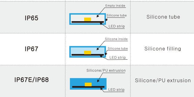
What Does the IP Rating Actually Tell You?
IP stands for Ingress Protection 1. The first digit rates dust resistance (0–6). The second digit rates water resistance (0–9). For LED strips, you typically see IP20, IP54, IP65, IP67, and IP68. Here is a quick reference.
| IP Rating 2 | Dust Protection | Water Protection | Typical Use Case |
|---|---|---|---|
| IP20 | Limited | None | Indoor dry areas, coves, shelves |
| IP54 | Dust-protected | Splash-proof | Indoor kitchens, mild humidity |
| IP65 | Dust-tight | Low-pressure water jets | Sheltered outdoor, bathrooms |
| IP67 | Dust-tight | Temporary submersion (up to 1 m) | Outdoor exposed, rain gutters |
| IP68 | Dust-tight | Continuous submersion (depth varies) | Pools, fountains, underground |
Beyond the Rating: Protect the Weak Points
A strip rated IP67 along its body still fails if you leave an unsealed cut end exposed to rain. In our factory, we test finished assemblies—not just the strip itself—because the real-world failure happens at transitions. Use heat-shrink end caps with adhesive lining. Use IP-rated connectors or solder joints sealed with silicone potting. Make sure the power supply housing matches or exceeds the strip IP level.
Extreme Temperatures Change the Rules
Moisture protection is only half the story. Extreme cold makes some silicone sleeves stiff and brittle. Extreme heat softens adhesives and accelerates chemical degradation of encapsulants. When we develop strips for freezer installations, we specify low-temperature silicone rated to −40 °C. For sun-exposed façades, we use UV-stabilized materials that will not yellow or crack after two summers.
Temperature cycling 3 is another hidden threat. A strip mounted on an exterior wall in Melbourne might swing from 5 °C at night to 45 °C in direct afternoon sun. That repeated expansion and contraction works at seals over time. The solution is to use flexible silicone encapsulants rather than rigid epoxy, and to leave small expansion gaps at mounting points.
Salt Air and Chemical Exposure
Coastal and industrial environments add corrosion to the mix. Salt air attacks exposed copper pads and tin solder. Chemical fumes in factories can degrade plastic housings. For these cases, we recommend conformal-coated PCBs 4 inside silicone extrusion sleeves. This double barrier keeps corrosive agents away from the circuit. If your project is near the ocean or in a food processing plant, ask your supplier specifically about corrosion-resistant component finishes.
What heat dissipation features should I look for to prevent my high-power strips from failing early?
On our production line, we run thermal aging tests on every new strip design. One thing our engineers consistently find is that heat does more cumulative damage than any other single factor. A strip running just 10 °C above its rated junction temperature 5 can lose half its expected lifespan.
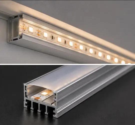
Look for aluminum-backed PCBs, compatibility with aluminum mounting channels, and adequate ventilation around the strip. High-power strips above 14 W/m should never be installed on wood, plastic, or insulated surfaces without a metal heat sink, because trapped heat degrades LED chips, shifts color temperature, weakens solder joints, and breaks down adhesive bonds over time.
Why Heat Is the Silent Killer
LEDs are efficient, but they still convert a portion of electrical energy into heat. At low power densities—say 5 W/m—the strip PCB and surrounding air handle this easily. At 20 W/m or above, heat builds fast. If the strip is inside a sealed cove, a closed aluminum profile without ventilation slots, or mounted flat against a painted drywall ceiling, the temperature climbs. You will not see damage immediately. But over weeks and months, you get accelerated lumen depreciation 6, color shift toward yellow, and eventually dead LEDs or lifted solder pads.
Choosing the Right Mounting Method
The mounting surface is your first heat sink. Aluminum channels are the gold standard. They conduct heat away from the PCB and spread it across a larger surface area. But not all channels are equal.
| Channel Type | Thermal Performance | Best For | Limitations |
|---|---|---|---|
| Surface-mount aluminum (open top) | Good | General indoor, moderate power | Dust collects in open channel |
| Recessed aluminum with diffuser | Good to very good | Architectural coves, ceilings | Diffuser traps some heat; needs airflow |
| Deep aluminum channel (U-profile) | Very good | High-power strips, continuous runs | Heavier, more expensive, needs proper mounting |
| Suspended aluminum with vent slots | Excellent | Industrial, high-ambient-temperature zones | Requires custom brackets |
| No channel (adhesive to surface) | Poor to moderate | Low-power accent lighting only | Not suitable above 10 W/m in enclosed spaces |
Ventilation and Airflow
Even with a good aluminum channel, airflow matters. If the channel is sealed inside a bulkhead with no air gaps, heat has nowhere to go. Our recommendation is to leave at least a 10 mm air gap above and below the channel when recessing into a ceiling or wall. For enclosed cabinetry, consider small ventilation holes at each end of the run or a thermostatically controlled mini fan for runs above 3 meters at high power.
Derating for High Ambient Temperatures
If the ambient temperature at the installation site is already high—for example, above a commercial oven, inside a greenhouse, or on a sun-facing exterior wall—you need to derate the strip. That means running it below its maximum rated power. A strip rated for 24 W/m at 25 °C ambient might need to run at 18 W/m or less at 50 °C ambient. Ask your supplier for a derating curve or thermal test data. If they cannot provide one, that is a red flag.
The Department of Energy Finding
Research published through the U.S. Department of Energy 7 has shown that driving LEDs at even slightly higher currents than recommended can reduce lifespan by as much as 50%. This applies directly to strip lighting. Overdrive happens when power supplies deliver voltage above spec, when too many strips are daisy-chained on a single output, or when dimming drivers produce current spikes. The fix is straightforward: use a regulated constant-voltage driver matched precisely to the strip's rated voltage, and never load a driver above 80% of its rated capacity.
How can I ensure my long-run LED installations maintain consistent brightness without voltage drop issues?
When our team helps contractors plan runs of 10, 15, or even 20 meters, voltage drop 8 is always the first technical conversation. We have seen too many projects where the first meter glows perfectly and the last meter looks noticeably dim. The cause is simple physics, but the fix requires planning before installation, not after.
For long LED strip runs, feed power from both ends or at multiple midpoints, use a properly sized cable gauge to minimize resistance losses, and never exceed the manufacturer's maximum single-feed run length. A voltage drop above 3% causes visible brightness differences, so calculate your total run, wire gauge, and injection points before you cut a single meter of strip.
Understanding Voltage Drop
Every conductor has resistance. When current flows through a long strip, the voltage at the far end is lower than at the feed point. LEDs at the far end receive less voltage, draw less current, and produce less light. On a 24 V strip, a 1 V drop at the end means a roughly 4% voltage loss. On a 12 V strip, the same 1 V drop is over 8%—much more visible.
This is why we always recommend 24 V or 48 V strips for runs above 5 meters. Higher voltage means lower current for the same wattage, which means less resistive loss along the copper traces.
Power Injection Strategies
The most reliable method is to inject power at multiple points along the run. Here are the common approaches.
| Strategy | Description | Best For | Complexity |
|---|---|---|---|
| Single-end feed | Power at one end only | Runs under 5 m (24 V) or 3 m (12 V) | Lowest |
| Dual-end feed | Power at both ends from same supply | Runs 5–10 m | Low |
| Mid-point injection | Power at center plus one or both ends | Runs 10–15 m | Moderate |
| Multiple injection points | Power every 5 m along the run | Runs above 15 m | Higher, but most reliable |
| Repeater/amplifier | Signal repeater with local power | Very long runs with dimming/RGB control | Highest |
Wire Gauge Matters
The cable between the power supply and the strip also has resistance. A thin 22 AWG wire over 10 meters adds significant drop before the current even reaches the strip. Use heavier gauge wire for longer distances. As a rule of thumb, for runs over 5 meters at moderate wattage, use 18 AWG or thicker. For high-power runs or distances over 10 meters from the driver to the first injection point, consider 16 AWG or 14 AWG.
Practical Tips from the Field
In projects we have supplied for commercial fitouts in Australia, contractors often run a central trunk cable along the ceiling and drop short leads to injection points every 5 meters. This keeps voltage consistent across the entire run and makes future maintenance easy—you can disconnect and replace one segment without disturbing the rest. For RGB or tunable-white strips, consistent voltage is even more critical because color mixing depends on each LED channel receiving the correct power. A voltage drop on one channel shifts the overall color, and you get visible color variation along the strip.
Always verify brightness uniformity with a test installation before committing to final mounting. A quick bench test with your actual cable lengths and power supply reveals any issues before they become permanent problems on the job site.
What quality control standards should I demand from my supplier to guarantee my project's long-term reliability?
Our QC team runs a 12-step inspection process on every production batch, from raw LED binning 9 to final packaging. We built this process because early in our export business, a single batch of poorly binned LEDs caused visible color inconsistency across a hotel lobby project in Germany. That one incident taught us that quality control is not optional—it is the foundation of every reliable installation.
Demand documented QC procedures that include LED binning for color consistency, thermal aging tests, adhesion pull tests, IP seal verification, and electrical safety certification. Ask for batch test reports, not just product datasheets. A reliable supplier will provide IES files, MacAdam ellipse ratings, and sample-based inspection data for every order you place.
LED Binning and Color Consistency
LEDs are semiconductor devices. Even from the same wafer, individual chips vary in color temperature, brightness, and forward voltage. Binning is the process of sorting LEDs into tight groups so that strips made from one bin look uniform. For architectural and commercial projects, you want LEDs within a 3-step MacAdam ellipse 10. This means the human eye cannot detect color differences between LEDs on the same strip or across strips from the same batch.
Ask your supplier what binning standard they use. If they cannot answer, or if they say "we use whatever the chip supplier sends," walk away. Color inconsistency is the number one complaint from contractors doing large-area installations, and it is entirely preventable at the manufacturing stage.
Certifications That Matter
Different markets require different certifications. Here are the most common ones for LED strips in professional projects.
| Certification | Region | What It Covers |
|---|---|---|
| CE | Europe | Electrical safety, EMC compliance |
| SAA / RCM | Australia | Electrical safety and regulatory compliance |
| UL / cUL | North America | Product safety testing |
| TÜV | Germany / Europe | Independent safety and quality verification |
| RoHS | Global | Restriction of hazardous substances |
| REACH | Europe | Chemical safety |
| IEC 62471 | Global | Photobiological safety of light sources |
For projects in Germany and Australia—our primary export markets—we maintain current CE and SAA certifications. If your supplier cannot provide valid, traceable certification documents for the specific product you are ordering, that is a serious risk. Certifications should match the exact model number, not just a general product family.
What to Ask for in a Batch Report
A good supplier provides more than a datasheet. For each production batch, request the following: LED bin code and color temperature range, forward voltage range, luminous flux per meter measured at 25 °C, CRI value with R9 score, adhesion test results, IP test results (with testing method noted), and thermal aging test summary. These documents let you verify that the product you receive matches what was specified. They also give you evidence to present to your own clients or project owners if questions arise later.
The Real Cost of Skipping QC
Skipping QC at the procurement stage shifts risk to the installation stage, where it costs far more to fix. Replacing a failed strip in a sealed cove ceiling takes hours of labor, plus patching, repainting, and potential damage to adjacent finishes. In one freezer project we supplied, the contractor used a secondary supplier for additional strips midway through. Those strips had different LED bins and lower adhesive quality. Within six months, sections peeled off and the color mismatch was visible to guests. The entire run had to be replaced. The cost of that rework was roughly ten times the original strip material cost.
Quality control is not a luxury. It is the cheapest insurance you can buy for a long-term installation.
Conclusion
Stable LED strip performance in harsh environments comes down to sealing, heat control, power stability, and strict QC. Get all four right at installation time, and your strips will run reliably for years.
Footnotes
- Provides a definition and explanation of the Ingress Protection standard. ↩︎
- Explains the meaning and importance of IP ratings for product protection. ↩︎
- Explains the phenomenon of temperature cycling and its effects. ↩︎
- Replaced 404 link with an authoritative Wikipedia page explaining conformal coating. ↩︎
- Defines junction temperature and its impact on LED lifespan. ↩︎
- Explains the concept of lumen depreciation in LED lighting. ↩︎
- Provides information about the Department of Energy's role in LED research. ↩︎
- Explains the electrical phenomenon of voltage drop in circuits. ↩︎
- Describes the manufacturing process of LED binning for color consistency. ↩︎
- Explains the MacAdam ellipse standard for LED color consistency. ↩︎

 English
 Spanish
 German
 Russian
 Arabic
 French
 Portuguese