
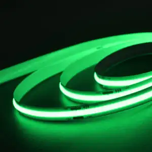
We have spent years helping contractors solve one persistent complaint: visible hotspots that ruin otherwise beautiful lighting installations.
COB LED strip lights offer more continuous lighting because they mount hundreds of tiny LED chips directly onto the flexible circuit board and cover them with a phosphor coating, merging individual points into a seamless, dotless line of light that traditional SMD LED strips cannot match.
Below, I break down the engineering, the real-world visual differences, and the trade-offs you should weigh before specifying COB for your next project.
How does the chip-on-board design eliminate the visible spotting I usually see in SMD strips?
One lesson I learned early, when our team was troubleshooting a hospitality refit, is that no diffuser cover fully erases visible hotspots once SMD spacing is too wide.
The chip-on-board design eliminates visible spotting by placing LED chips so close together—often over 500 per meter—that no gap remains for dark spots, then sealing them under a continuous phosphor layer that blends each chip's output into uniform illumination.
What Exactly Is Chip-on-Board Technology?
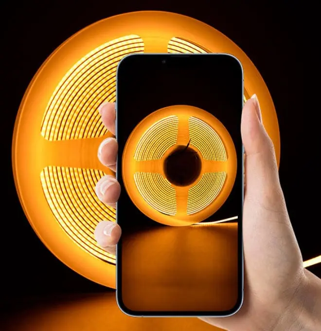
COB stands for Chip-on-Board. Instead of packaging each LED die inside its own plastic housing and then soldering those housings onto a strip at intervals, COB mounts the bare dies directly onto the flexible circuit board 1. The dies sit so closely together that they almost touch. A single, unbroken phosphor coating 2 then covers the entire row.
This approach turns many point light sources into what the eye perceives as one continuous surface emitter. Traditional SMD strips, by contrast, space individual LED packages anywhere from 5 mm to 17 mm apart. Even at 120 LEDs per meter, each package is still a distinct bright dot separated by a dark gap.
Why Spacing Is the Root Cause of Spotting
Think of it this way. If you line up candles 15 mm apart, you see individual flames. Move them to 1 mm apart, and you see a wall of fire. COB applies the same principle. The LED chip density is so high that the human eye can no longer resolve individual sources.
Comparing COB and SMD Under Real Conditions
| Feature | Traditional SMD Strip (e.g., 2835) | COB LED Strip |
|---|---|---|
| Typical LED density | 60–120 LEDs/m | 320–528 LEDs/m |
| Visible dot effect | Yes, especially close-up | No — dotless LED strip appearance |
| Phosphor coverage | Individual lens per LED | Continuous phosphor coating over all chips |
| Beam angle | ~120°–140° | ~180° (wider beam angle 3) |
| Need for heavy diffuser | Often required | Minimal or none |
The Role of the Phosphor Layer
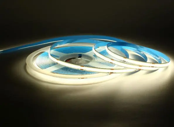
The phosphor coating is not just for color conversion. It acts as a built-in light diffusion layer. Because it is continuous rather than segmented, it smooths the transitions between each tiny chip. In our production runs, this is where quality control matters most. If the phosphor layer is uneven, you get brightness ripples. When we calibrate our coating process for export orders heading to Germany or Australia, we measure luminance uniformity along the strip with a goniophotometer 4 to make sure the line stays visually seamless.
Close-Range Visibility Is Where COB Wins
From three meters away, a well-diffused SMD strip can look acceptable. But in under cabinet lighting, cove details, or vanity mirrors—anywhere the viewer is within one meter—the individual LED points become obvious. COB strips solve this. They deliver a clean, unbroken glow that needs no heavy diffuser to hide dot patterns. For contractors who install lighting in high-end kitchens and bathrooms, this matters every single day.
Will COB technology provide the seamless linear effect my high-end architectural projects demand?
A buyer we work with in Sydney once told me he lost a tender because the architect rejected SMD strips after a mock-up revealed visible dot patterns behind a frosted glass feature wall.
Yes. COB technology provides the seamless light output that architects specify because its continuous emitting surface removes pixelation, offers a wider beam angle of roughly 180 degrees, and often eliminates the need for bulky aluminum diffuser profiles.
Where Architects Need Seamless Lines
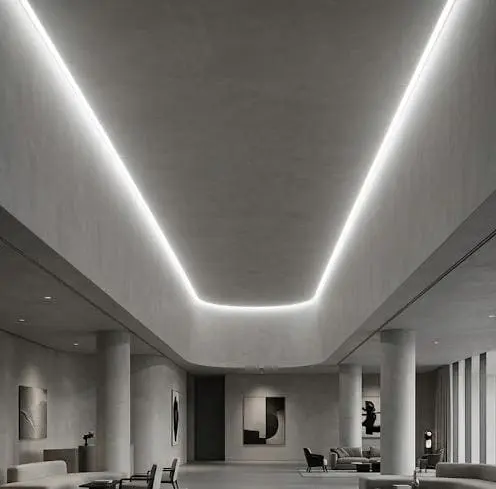
Architectural lighting increasingly uses exposed or semi-exposed strips. Feature walls with translucent panels, floating staircases with recessed coves, and backlit mirrors all place the light source within the viewer's direct line of sight. In these applications, any dot or bright spot is a design flaw, not just an engineering shortcoming.
Why COB Meets the Brief
COB strips deliver a line of light so even that designers sometimes call it "neon-like" without the fragility or minimum-bend limitations of glass neon. The wider beam angle—around 180 degrees versus roughly 140 degrees for many SMD strips—means the light fans out broadly and fills a channel or cove more evenly.
Diffuser Profile Savings
When we quote for project-based supply, the channel and diffuser accessories can represent a significant portion of the total material cost. With COB, many of our contractor clients in Australia specify shallower profiles or skip the milky diffuser altogether, choosing a clear lens instead. That cuts cost and installation depth—two things that matter in ceiling coves where space is tight.
| Application | SMD Strip Requirement | COB Strip Requirement |
|---|---|---|
| Shallow cove (< 30 mm depth) | Deep milky diffuser profile needed | Shallow or clear profile sufficient |
| Backlit translucent panel | Risk of dot visibility through panel | Seamless glow, no dot shadows |
| Floating shelf accent | Must hide strip completely | Strip can be semi-exposed |
| Mirror perimeter lighting | Frosted channel mandatory | Can run bare or with minimal cover |
| Retail display shelf | Diffuser adds bulk | Slim, clean integration |
A Practical Design Consideration
One thing I always flag for specifiers: seamless light output does not mean you can ignore optics entirely. If you are illuminating a curved surface, the strip still needs to follow the radius smoothly. COB strips are generally more flexible than rigid SMD strips of similar width, which helps. But tight bends below the rated minimum radius will still cause issues—whether hot spots, solder-joint stress, or phosphor cracking. We prototype curved sections for clients before committing to a full production run to confirm the bend works.
Can I achieve better color consistency across my long-run installations by switching to COB?
During a recent order review for a 200-meter hotel corridor project, I noticed our QC team was spending extra time on bin matching to guarantee that every reel of SMD strip fell within a tight color tolerance—an issue that COB packaging handles more gracefully by design.
COB strips improve color consistency in long-run installations because the continuous phosphor coating averages out minor chip-to-chip variations, and the high LED chip density smooths any individual outlier, producing visually stable color temperature across the entire run.
Why Color Shifts Happen in Traditional Strips
Color inconsistency in SMD LED strips 5 comes from two main sources:
- Bin-to-bin variation — LED chips are sorted into color bins after manufacturing. Even within one bin, slight differences exist. When chips are spaced far apart, each one's individual hue is visible, and the eye picks up the shift.
- Voltage drop over distance — On long runs, voltage decreases toward the far end. Lower voltage shifts the color temperature slightly, and when combined with bin variation, the result can be visible warm-to-cool drift across a hallway or retail run.
How COB Addresses Both Problems
The phosphor coating in a COB strip acts as a physical averaging filter. Hundreds of chips contribute to every centimeter of visible light. If one chip is a fraction of a degree off in correlated color temperature 6, its neighbors dilute the error. The eye sees the aggregate, not the outlier.
For voltage drop, COB strips still face the same electrical reality as SMD strips. However, many COB products are engineered with constant-current segments and thicker copper traces on the flexible circuit board to minimize drop. On our production line, we test strips at full rated length to confirm that the delta in color temperature from start to end stays within acceptable limits before shipping.
Practical Tips for Long Runs
| Challenge | SMD Strip Approach | COB Strip Approach |
|---|---|---|
| Bin matching across reels | Manual sorting; risk of mismatch | Phosphor averaging reduces visible mismatch |
| Voltage drop over 10 m+ | Requires power injection every 5–10 m | Still needs injection, but color shift is less visible |
| Batch-to-batch consistency | Tight QC on binning required | Phosphor layer provides an extra consistency buffer |
| Visual uniformity at joints | Solder joints may show bright/dark spots | Continuous phosphor hides joint transitions |
A Word of Caution
COB is not a magic fix for poor binning or sloppy power design. If the underlying chip quality is low, the phosphor layer can only mask so much. When we source dies for our mid-to-high-end product lines, we still specify tight MacAdam-ellipse bins 7. The phosphor averaging is a bonus layer of safety, not a replacement for good raw materials. Contractors who buy the cheapest COB strip available may still encounter color drift—especially on runs beyond 15 meters without proper power injection.
How does the flexibility of COB strips help me avoid light discontinuity in my custom-sized project builds?
I recall a tricky retail fitout quote where the client needed strips cut to 87 specific lengths—none of them standard—and the SMD strip's cut interval would have left visible dark gaps at every junction point.
COB strips offer finer cut intervals—often every 25 mm or less—and their flexible circuit board bends smoothly around curves, so custom-length segments join without dark spots or visible breaks, keeping light continuous across non-standard installations.
Cut Intervals Matter More Than You Think
Standard SMD strips typically allow cuts every 50 mm to 100 mm. That sounds small, but when a designer specifies a shelf that is 437 mm long, you either cut short and leave a visible dark zone at the end, or you overlap and create a hot spot. COB strips can often be cut every 25 mm or even less, depending on the product. This tighter interval means your installed length matches the design length far more closely.
Flexibility and Bend Radius
COB strips are built on a narrower, thinner flexible circuit board with no bulky SMD packages protruding from the surface. This gives them a tighter achievable bend radius. For S-curves in signage, curved cabinet interiors, or radius coves, COB strips follow the contour without kinking. When we develop custom-sized builds for our OEM partners, we specify the minimum bend radius in the product datasheet and test sample curves before mass production.
How Connectors and Joints Affect Continuity
Even with COB, you may need to join segments. The advantage is that the continuous phosphor surface minimizes the visual break at a solder joint. With SMD strips, a joint between two segments often falls between two LEDs—creating a noticeable dark line. With COB, the high chip density means there is almost always an emitting chip right at the cut edge, so when two segments butt together, the seam nearly disappears.
Step-by-Step: Avoiding Discontinuity in Custom Builds
- Measure precisely. Get exact dimensions from the site, not from drawings alone.
- Choose a COB strip with a fine cut interval. Aim for 25 mm or less for maximum flexibility.
- Plan power injection points. For runs over 5 meters, inject power mid-run to maintain uniform illumination.
- Test bends on a sample. Before committing to a full order, bend a test piece to the project's tightest radius.
- Use solderless connectors rated for COB. Standard SMD connectors may not fit the narrower pad layout.
When SMD Might Still Be the Right Call
Not every project needs COB. If your installation is straight, hidden behind a deep opaque diffuser, and budget is the primary driver, a quality SMD strip at 120 LEDs per meter may serve perfectly well. COB earns its premium in visible, curved, or tightly dimensioned applications where every millimeter of light continuity counts.
Conclusion
COB LED strip lights 8 deliver more continuous lighting through extreme chip density, a seamless phosphor layer, and flexible construction—solving visible hotspot and color consistency problems that traditional SMD strips struggle with.
Footnotes
- Provides background on the material and design of flexible PCBs. ↩︎
- Details the material responsible for light diffusion and color conversion in LEDs. ↩︎
- Defines an important optical property influencing light distribution. ↩︎
- Describes a specialized instrument used for precise light measurement. ↩︎
- Compares traditional SMD LED technology with COB for better understanding. ↩︎
- Replaced unknown HTTP status link with an authoritative Wikipedia article on correlated color temperature. ↩︎
- Replaced 404 link with an explanation of SDCM (MacAdam ellipse) from a lighting manufacturer. ↩︎
- Explains the fundamental technology and benefits of COB LED strips. ↩︎



 English
 Spanish
 German
 Russian
 Arabic
 French
 Portuguese