We frequently see project delays on production floor caused simply by mismatched connectors. When integrating high-density lighting systems, ignoring the specific mechanical requirements of Chip-on-Board technology often leads to installation failures.
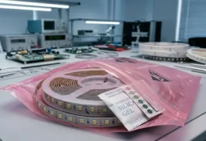
To consult a supplier effectively, you must explicitly share your COB strip’s PCB width and thickness, inquire about transparent housings to prevent dark spots, verify the connector’s amperage rating for high-density loads, and request samples to perform mechanical pull tests on the delicate phosphor coating.
Let’s break down the specific technical questions you need to ask to ensure a seamless installation.
In engineering lab, we have found that even a 0.5mm variance in width can cause a connection to fail during thermal expansion. Guesswork here is dangerous.
You must provide the supplier with the exact PCB width (typically 8mm or 10mm), the copper thickness (oz), and the pin configuration. Crucially, specify that you are using COB strips, as the continuous phosphor gel layer requires connectors with specific clearance heights unlike standard SMD tapes.
The Unique Geometry of COB Strips
When you source connectors for standard SMD (Surface Mounted Device) LED strips, you are usually dealing with discrete components soldered onto a flexible board. There are gaps between the chips where a connector clamp can safely sit. However, Chip-on-Board (COB) strips are different. They feature a continuous layer of phosphor gel that covers the diodes to create that seamless "dotless" effect.
This gel layer adds height and fragility to the top surface of the PCB. If you do not specify this to your supplier, they might send you standard connectors designed for flat SMDs. These standard clamps often fail to close properly over the thicker gel, or worse, they crush the phosphor coating, damaging the underlying chips.
Critical Dimensions to Verify
To avoid this, you need to provide a comprehensive data sheet to your supplier. Do not just say "10mm strip." You need to be specific about the tolerances.
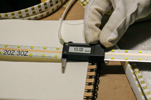
- PCB Width: Is it exactly 10mm, or is it 10.2mm including the silicone waterproofing?
- PCB Thickness: High-quality project strips often use 3oz or 4oz copper, making the board thicker (0.35mm) than the standard 2oz (0.25mm) consumer grade.
- Pad Spacing: The distance between the copper solder pads varies between manufacturers.
Connector Compatibility Matrix
We use the following checklist internally when matching connectors to new strip designs. You can use this to guide your supplier consultation:
| Specification | Standard Requirement | COB Specific Concern |
|---|---|---|
| PCB Width | 8mm / 10mm | Must match exactly to prevent side-to-side slippage. |
| Pin Count | 2-pin (Single Color) / 3-pin (CCT) | Ensure pins align with the solder pads, not the gel. |
| Clamping Mechanism | Top-down pressure | Needs "piercing" or side-biting to avoid crushing gel. |
| Height Clearance | Low profile | Must accommodate the added height of the phosphor layer. |
The "Piercing" vs. "Pressure" Debate
When discussing specs, ask your supplier if their solution uses Insulation Displacement Contact (IDC) technology. These are often referred to as "piercing" connectors. Instead of pressing down on the top of the strip (which is risky for COB gel), these connectors have tiny teeth that pierce the PCB from the bottom or the sides. This ensures a solid electrical connection with the copper tracks without disturbing the delicate phosphor layer on top.
How Do I Confirm With the Supplier That Their Connectors Won't Create Dark Spots in the Lighting Run?
Our clients, especially lighting designers, despise visible joints that interrupt the seamless line of light they promised their customers. A dark spot ruins the premium feel.
You should explicitly request "gapless" or "butt-joint" connectors featuring transparent polycarbonate housings. Ask the supplier if the connector body sits over the diodes or between them, and verify that the housing material has a high light transmission rate to minimize shadowing at the connection point.
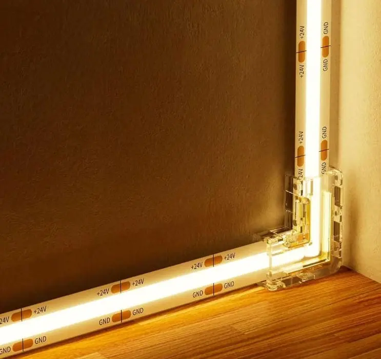
The Aesthetics of Continuity
The primary selling point of COB strips is the "dotless" continuous line of light. However, bulky connectors can instantly negate this benefit. If a connector has a solid white or black plastic housing that clamps over the top of the LED tape, it will block the light output for approximately 5mm to 10mm. In a high-end architectural cove or under-cabinet installation, this creates a visible "break" or dark spot every time you join two strips.
Evaluating Housing Transparency
When consulting your supplier, ask about the material composition of the connector housing. You are looking for clear Polycarbonate (PC) materials. While no connector is 100% invisible, a transparent housing allows the light from the COB strip to pass through the clamp mechanism, significantly reducing the shadow effect.
However, be critical. Some "transparent" connectors are actually cloudy or frosted, which still diffuses the light differently than the bare strip, creating a color shift at the joint.
Gapless vs. Wired Connections
There are generally two ways to join strips, and your choice affects the visual outcome:
- Strip-to-Wire: Used for corners or jumping gaps (e.g., over a rangehood). These inevitably create dark spots because there is wire between the strips.
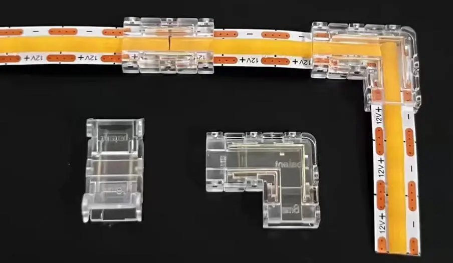
- Strip-to-Strip (Gapless): These butt the two strips directly against each other inside the connector.
Visual Impact Comparison
Here is how different connector styles impact the visual consistency of your lighting run:
| Connector Style | Housing Material | Visual Result | Best Application |
|---|---|---|---|
| Standard Clamp | Opaque White Plastic | 10mm Dark Spot | Hidden areas, top of cabinets. |
| Slim Clear Clamp | Transparent PC | < 2mm Shadow | Visible channels, aluminum profiles. |
| Butt-Joint (Gapless) | Transparent PC | Near Seamless | Continuous linear runs. |
| Soldered Joint | None (Solder + Tube) | Seamless | High-end custom fixtures. |
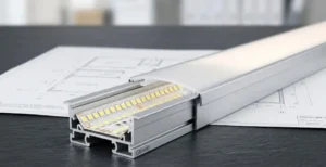
Fitting Inside Channels
Another aspect of "dark spots" is the physical fit. Many COB connectors are wider than the strip itself. If you are using a narrow aluminum profile (e.g., a 12mm wide channel for a 10mm strip), a connector that is 14mm wide simply won't fit inside the channel. This forces you to place the connector outside the channel or cut the channel, both of which look unprofessional.
Always ask the supplier for the external dimensions (width and height) of the connector housing. Verify these against the internal dimensions of your aluminum profiles. If the connector is too tall, it might press against the diffuser cover, creating a bright "hot spot" that looks just as bad as a dark spot.
What Should I Ask About Current Handling Capabilities to Ensure Safety for High-Density Strips?
We test high-density strips daily and know they generate significant heat while drawing heavy current loads. A weak connector becomes a fire hazard.
Ask for the connector’s maximum amperage rating and verify it exceeds the total current draw of your run. Specifically, inquire about the contact resistance specifications and whether the terminal material is phosphor bronze or standard copper to ensure it can handle the heat without deforming.
The High-Density Current Challenge
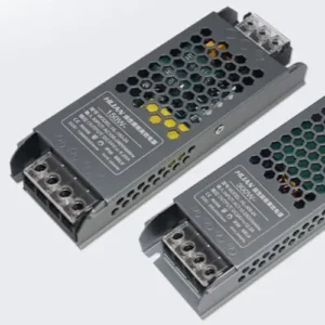
High-density COB strips (often 320 to 480 chips per meter) are power-hungry. A typical high-output COB strip might consume 14W to 20W per meter. If you are running a 5-meter length at 24V, you are pushing approximately 3 to 4 Amps through the connection point.
Many cheap connectors on the market are rated for only 2A or 3A. If you use an under-rated connector, it becomes a bottleneck. The resistance at the contact point increases, generating heat. In extreme cases, we have seen connectors melt their housings or scorch the PCB, leading to failure.
Calculating Your Safety Margin
When talking to suppliers, do not accept a generic "it works for LED strips" answer. You need data.
- Ask: "What is the max current rating (Amps) per pin?"
- Calculate: Total Wattage of Run / Voltage = Total Amps.
- Verify: Ensure the connector rating is at least 20% higher than your calculated load.
Voltage Drop and Contact Resistance
High-density strips are incredibly sensitive to voltage drop. Even a small amount of resistance at the connector can cause the voltage to dip from 24V to 23V immediately after the connection. This results in the second strip being visibly dimmer than the first.
Ask your supplier for the Contact Resistance value. A high-quality professional connector should have a contact resistance of less than 30 milliohms (mΩ). If the supplier cannot provide this data, it suggests they may not be testing their products for professional-grade applications.
Thermal Expansion Mismatch
Another technical nuance we deal with is thermal expansion. LED strips heat up when on and cool down when off. This cycle causes materials to expand and contract.
- The Problem: The copper PCB, the silicone gel, and the plastic connector housing all expand at different rates.
- The Risk: Over time, this movement can loosen the metal contacts inside the connector.
- The Solution: Ask if the connector uses Phosphor Bronze contacts. This material has excellent spring properties (elasticity) and maintains a tight grip even after thousands of thermal cycles, unlike cheaper metals that lose their "spring" over time.
Safety Checklist for Suppliers
Use this table to vet the safety claims of your supplier:
| Feature | Minimum Requirement | Why it Matters |
|---|---|---|
| Max Current | > 5 Amps | Prevents overheating in long runs. |
| Housing Material | Nylon 66 / Polycarbonate (UL94 V-0) | Flame retardant; won't catch fire if overheated. |
| Contact Material | Phosphor Bronze / High-Copper Alloy | Maintains grip during thermal expansion. |
| Voltage Rating | 0-36V DC | Compatible with standard 12V/24V systems. |
How Do I Request Samples to Test the Mechanical Grip Strength on My Specific LED Tape?
Before we ship any bulk order, we perform rigorous pull tests to ensure the connectors won't detach during installation. You must validate this yourself.
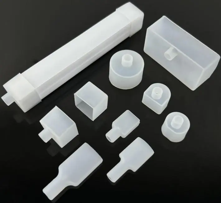
Request a sample kit containing both strip-to-wire and strip-to-strip types, then perform a manual pull test to check for slippage. Inspect the COB gel after removal to ensure the connector teeth haven't caused micro-cracks that could lead to blue light leakage or color shifting.
Why You Must Test on Your Strip
Connectors are not universal. A connector that grips a 10mm strip from Factory A might slip off a 10mm strip from Factory B because of slight differences in PCB thickness or the texture of the solder mask backing. We strongly advise against buying connectors and strips from different sources without testing them together first.
The "Pull Test" Protocol
When you receive your samples, do not just light them up. You need to stress-test them.
- Install the Connector: Follow the instructions to attach it to a scrap piece of your COB strip.
- The Tug: Hold the connector in one hand and the strip in the other. Apply a firm, steady pull. You aren't trying to rip it apart like a strongman, but it should withstand the weight of the strip hanging freely plus some tension (approx. 5-10 Newtons of force).
- The Wiggle: Wiggle the strip side-to-side while it is lit. If the light flickers, the contact mechanism is poor.
Checking for "Blue Light Leakage"
This is a specific issue with COB technology. The white light you see is actually blue light from the diode passing through the yellow phosphor gel.
If the connector clamps down too hard, it can crack the dried phosphor gel. Even a microscopic crack allows raw blue light to escape.
- Test: Connect the strip and turn it on.
- Inspect: Look closely at the connection point. Do you see any tiny pinpricks of blue light?
- Conclusion: If you see blue leaks, the connector is mechanically incompatible—it is crushing the gel layer.
Batch Consistency and Future-Proofing
Finally, ask your supplier about their tooling stability.
- "Is this connector produced from a public mold or your private mold?"
- "Will this exact model be available in 2 years?"
Public mold connectors (generics) often change slightly from batch to batch because the factory buys them from the cheapest sub-supplier that week. For project-grade work, you need a supplier who controls their supply chain to ensure the connector you buy today fits the strip you buy next year.
Sample Evaluation Scorecard
When you get your samples, score them on these criteria before approving a bulk purchase:
| Test Criteria | Pass Indicator | Fail Indicator |
|---|---|---|
| Insertion Force | Firm click or snap. | Too loose or requires pliers to force shut. |
| Grip Strength | Holds strip weight + tension. | Strip slides out with gentle pull. |
| Light Continuity | Steady light while wiggling. | Flickering or intermittent connection. |
| Gel Integrity | No cracks or blue leaks. | Visible damage to yellow phosphor surface. |
Conclusion
Consulting a supplier for COB connectors requires moving beyond basic compatibility. By demanding specific data on PCB tolerances, verifying current handling for safety, and physically testing for grip strength and gel damage, you ensure your lighting projects remain safe, durable, and visually flawless.