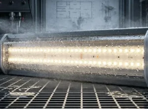
We often test LED strips against extreme heat to ensure they survive harsh climates like Australia's 1, knowing that overheating leads to rapid failure.
You must prioritize the PCB thermal conductivity (aim for aluminum substrates >190 W/mK), copper weight (minimum 2oz or 3oz), and wattage density. Crucially, verify the maximum junction temperature (Tj) delta at 45°C ambient to prevent rapid lumen degradation and ensure the adhesive backing is rated for high-heat cycling.
Let's break down the specific technical metrics you need to check before installation.
Does the PCB width and copper weight significantly impact the thermal management of high-density COB strips?
When we engineer high-density strips, we see that narrow boards trap heat, causing premature dimming in hot environments if the copper layer is too thin.
Yes, PCB width and copper weight are critical. A wider PCB (10mm+) increases surface area for heat transfer, while heavier copper (3oz vs. 2oz) spreads heat laterally, preventing hotspots. This combination significantly lowers the junction temperature, ensuring stability even when ambient temperatures spike.
When we analyze the failure rates of LED strips in high-heat regions, a recurring culprit is the physical design of the Printed Circuit Board 2 (PCB). In the context of Chip-on-Board (COB) technology, where hundreds of chips are packed densely together, the PCB acts as the primary highway for heat to escape the delicate LED dies. If this highway is too narrow or lacks sufficient lanes (copper thickness), traffic jams occur—in the form of thermal hotspots.
The Physics of Copper Weight
Copper is an excellent thermal conductor, but its effectiveness relies on mass. In the LED industry, we measure copper thickness in ounces (oz). Standard strips often use 1oz copper, which is sufficient for low-power accent lighting in air-conditioned rooms. However, for the Australian market, where ambient temperatures can hit 45°C, 1oz is often inadequate.
Our engineering data shows that upgrading from 2oz to 3oz copper can reduce the operating temperature of the strip by several degrees. This might sound small, but in the exponential world of semiconductor degradation, every degree counts. The thicker copper layer allows heat to spread laterally across the entire length of the strip rather than concentrating directly under the chips. This lateral spreading is vital before the heat can be transferred vertically into the aluminum profile.
Width Equals Surface Area
The width of the PCB is equally important. A narrow 5mm or 8mm PCB has physically less surface area to transfer heat to the mounting surface. In our product development, we strongly recommend a minimum width of 10mm for any high-density COB strip intended for warm climates. The wider footprint maximizes the contact area with the aluminum channel, facilitating faster heat exchange.
Critical Thinking: The Trade-off
However, simply increasing copper weight isn't a magic bullet. Thicker copper makes the strip less flexible and harder to install around tight corners. It also increases the cost. Therefore, you must balance the need for thermal management with installation requirements. For straight runs in outdoor pergolas or eaves, prioritize the heaviest copper and widest PCB available.
Copper Weight vs. Heat Dissipation Efficiency
| PCB Copper Weight | Thermal Conductivity Efficiency | Recommended Application | Max Power Density (Approx.) |
|---|---|---|---|
| 1oz (35µm) | Low | Indoor, Climate Controlled | < 9.6 W/m |
| 2oz (70µm) | Medium | Standard Commercial | 10 - 14 W/m |
| 3oz (105µm) | High | Outdoor / High Ambient Temp | 15 - 20 W/m |
| 4oz (140µm) | Very High | Industrial / Extreme Heat | > 20 W/m |
How do I verify if the adhesive backing can withstand extreme ambient heat without peeling?
We frequently receive reports of strips detaching in hot climates because standard tapes fail when the adhesive softens under the intense Australian sun.
Verify the adhesive's thermal rating in the datasheet, looking for high-bond tapes like 3M VHB or TESA rated for temperatures above 80°C. Standard adhesives lose viscosity at high heat, so request peel-strength test reports specifically conducted at elevated temperatures to ensure long-term adhesion.
The adhesive backing is often the most overlooked component of an LED strip, yet it is the most common point of failure in hot environments. When we source raw materials, we see a vast difference in quality between generic "red tape" adhesives and genuine industrial-grade bonding agents. In the Australian summer, the surface temperature of an aluminum profile installed under a veranda or near a window can easily exceed 60°C or 70°C. At these temperatures, standard adhesives undergo a phase change, becoming gooey and losing their grip.
The Chemistry of Heat and Glue
Most pressure-sensitive adhesives (PSAs) used on LED strips are acrylic-based. While acrylics are generally durable, their viscosity is temperature-dependent. Inferior adhesives have a low glass transition temperature. Once the ambient heat pushes past this threshold, the molecular bonds loosen. Gravity then takes over, and the strip begins to sag. This is not just an aesthetic issue; when a strip detaches from its aluminum profile, it loses its heat sink. The LED chips then overheat rapidly and burn out.
Coefficient of Thermal Expansion (CTE) Mismatch
Another factor we monitor is the Coefficient of Thermal Expansion (CTE). The LED strip (copper and silicone) expands at a different rate than the aluminum profile it is stuck to. In a climate with massive temperature swings—like a 40°C day dropping to a 20°C night—this differential expansion creates shear stress along the adhesive line. Over thousands of cycles, a weak adhesive will fatigue and delaminate.
Verifying the Datasheet
Do not simply accept "3M tape" as a specification. 3M makes hundreds of tapes. You need to look for specific series codes. For example, the 300LSE series is excellent for low-surface-energy plastics but may not be the best for high-heat metal bonding compared to the VHB (Very High Bond) series. We recommend asking your supplier for the specific datasheet of the tape used, not just the LED strip.
Common Adhesive Types and Temperature Limits
| Adhesive Type | Typical Max Temp (Short Term) | Typical Max Temp (Long Term) | Suitability for AU Summer |
|---|---|---|---|
| Generic "Yellow" Tape | 60°C | 40°C | Avoid |
| Standard 3M 200MP | 120°C | 80°C | Acceptable |
| 3M 300LSE | 140°C | 90°C | Good |
| 3M VHB (Acrylic Foam) | 150°C | 120°C | Best (Heavy Duty) |
| TESA Thermal Tape | 180°C | 100°C | Excellent (Conductive) |
What maximum operating temperature should I look for in the datasheet for outdoor installations?
Our lab tests show that standard strips rated for mild climates often degrade rapidly when exposed to the compounding heat of direct sunlight and electrical resistance.
Look for a maximum operating temperature (Ta) of at least 60°C, though 80°C is preferable for direct sun exposure. This headroom accounts for the internal heat rise (Delta T) added to the ambient 45°C Australian summer heat, keeping the LED junction temperature within safe limits.
Reading an LED datasheet requires a critical eye, especially regarding temperature ratings. There is often confusion between Ambient Temperature (Ta), Operating Temperature (Top), and Junction Temperature (Tj). When we design a product for export to hot climates, we calculate the thermal budget based on the worst-case scenario.
yellow phosphor coating 4
Understanding the Thermal Stack
Imagine a hot day in Western Australia. The air temperature (Ta) is 45°C. However, the air inside an enclosed aluminum channel or under a dark eave can be significantly hotter, perhaps 55°C. Now, turn on the LED strip. The electrical resistance generates internal heat. This creates a "Delta T" (temperature rise) above the ambient environment.
If a high-wattage COB strip raises its own temperature by 30°C during operation, and the ambient air is 55°C, the actual temperature at the PCB level is 85°C. If the manufacturer's datasheet states the maximum operating temperature is only 60°C, that product is destined to fail. You need a buffer.
industry standard is L70 5
The Solar Load Factor
We also advise clients to consider the "solar load." If the installation is outdoors and exposed to indirect or direct sunlight, the UV radiation heats the materials independently of the air temperature. Black or dark-colored surfaces absorb more heat. Therefore, the "ambient" temperature the strip experiences is actually the micro-climate inside the channel, not the weather report temperature.
Reading the Derating Curve
A professional datasheet will include a derating curve. This graph shows how much power (and thus brightness) the LED can safely handle as the temperature rises. A robust product might deliver 100% brightness at 25°C but should automatically reduce current or be manually dimmed if the temperature hits 60°C to protect the chips. If a supplier cannot provide a derating curve or a high maximum operating temperature rating, it is a red flag for high-heat applications.
Critical Analysis: Ta vs. Tj
Ultimately, the most critical metric is the Junction Temperature (Tj)—the temp at the core of the LED chip. Most LEDs fail if Tj exceeds 120°C. Your goal is to keep Tj below 85°C for longevity.
- Formula: Tj = Ta + (Power × Thermal Resistance).
- If Ta is high (Australia), you must lower Power or lower Thermal Resistance (better materials) to keep Tj safe.
Will high ambient temperatures drastically reduce the lumen maintenance lifespan of my LED strips?
We warn our clients that ignoring thermal management in hot regions accelerates phosphor degradation, turning bright white light into a dim, blueish hue within months.
lumen maintenance 6
Yes, high ambient temperatures accelerate lumen depreciation (L70). For every 10°C rise above the optimal junction temperature, the lifespan can be cut by 50%. Effective heat dissipation via aluminum profiles is essential to maintain brightness and color consistency over the product's rated life.
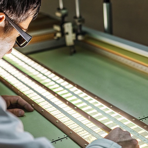
Lumen maintenance is the technical term for how long an LED stays bright. The industry standard is L70, which indicates the time it takes for the light output to drop to 70% of its original brightness. At our factory, we run accelerated aging tests, and the results are always consistent: heat is the number one killer of LED longevity.
Coefficient of Thermal Expansion 8
The Mechanics of Degradation
Inside a white COB LED, there is a blue LED chip covered by a yellow phosphor coating. The mixture of blue light and yellow phosphor creates white light. High heat damages both the silicone encapsulant and the phosphor itself.
- Phosphor Carbonization: Excessive heat causes the phosphor to degrade and darken. This reduces light output and causes a color shift.
- Silicone Yellowing: The clear silicone over the COB strip can turn yellow or brown under sustained high heat (and UV exposure), acting like a dirty filter that blocks light.
- Blue Shift: As the phosphor fails, more raw blue light escapes, changing the color temperature from a warm 3000K to a harsh, cool blue.
The Arrhenius Equation in Practice
Without getting too bogged down in physics, the degradation of LED materials follows the Arrhenius equation, which describes how reaction rates increase with temperature. A simplified rule of thumb we use in the industry is that for every 10°C increase in junction temperature above the rated limit, the expected lifespan is halved.
If a strip is rated for 50,000 hours at a junction temperature of 85°C, but it runs at 95°C due to the Australian summer heat and poor heat sinking, you might only get 25,000 hours. If it hits 105°C, you might be down to 12,000 hours—barely over a year of 24/7 operation.
300LSE series 9
Mitigation Strategies for Installers
To combat this, we strongly advise against installing high-wattage COB strips (anything over 10W/m) directly onto wood or plaster in hot climates. You must use an aluminum profile. The profile acts as a thermal reservoir, absorbing the heat peak during the day and dissipating it. Furthermore, consider under-driving the LEDs. Using a dimmer to run the strips at 80% brightness can significantly lower the thermal load while barely affecting the perceived brightness to the human eye.
Impact of Temperature on Lifespan (Estimated)
| Junction Temp (Tj) | Estimated L70 Lifespan | Color Shift Risk |
|---|---|---|
| 65°C | > 60,000 Hours | Very Low |
| 85°C | ~ 50,000 Hours | Low |
| 95°C | ~ 25,000 Hours | Moderate |
| 105°C | ~ 12,000 Hours | High (Blue Shift) |
| 125°C | < 5,000 Hours | Critical Failure |
Conclusion
To ensure longevity in Australian heat, prioritize thermal data over brightness. Select heavy copper PCBs, high-temp adhesives, and robust aluminum profiles to protect your installation investment.
VHB (Very High Bond) 10
Footnotes
- Official Australian government climate records for extreme temperature context. ↩︎
- Global trade association for the printed circuit board and electronics industries. ↩︎
- Educational explanation of the semiconductor physics behind blue light-emitting diodes. ↩︎
- General background on the chemical compounds used to produce white light in LEDs. ↩︎
- Lighting industry standard for measuring the useful life of LED products. ↩︎
- Official government resource explaining LED performance and light output over time. ↩︎
- News coverage of extreme heat events in the Western Australia region. ↩︎
- Scientific background on how materials expand and contract with temperature changes. ↩︎
- Product specifications for low-surface-energy acrylic adhesive series. ↩︎
- Technical documentation for high-strength acrylic foam bonding tapes. ↩︎