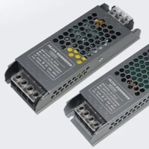
We usually catches the same issues customers report from the field — dead segments, flickering zones, and dim tails on LED strips power supply and voltage compatibility 1. These problems frustrate installers and erode trust in a project. But the good news is most of them follow a predictable pattern.
When some LEDs on your strip are not working, start by checking the power supply and voltage compatibility, then inspect connectors and solder joints for damage, and finally isolate the faulty section. Most partial failures trace back to a broken circuit, a bad joint, or voltage drop along the run.
This guide walks you through a clear decision-tree process solder joints 2. We will cover symptom identification, step-by-step diagnosis, hands-on repair, and guidance on when to replace rather than fix. Let's start with the most common scenario: only part of your strip has gone dark.
Why are only certain sections of my LED strip lights failing to turn on?
We see this question daily in our technical support inbox repeating parallel groups 3. A customer installs ten meters of strip, and everything looks great — until one section in the middle stays dark while the rest glows perfectly.
Certain sections fail because LED strips are wired in repeating parallel groups of three or more LEDs. When a solder joint, trace, or individual LED within one group breaks, only that group goes dark while the rest of the strip continues to work normally.

How LED Strip Circuits Are Structured
LED strips are not one continuous chain. They are divided into small segments, each containing a few LEDs and a current-limiting resistor 4. These segments are wired in parallel along two main copper traces — the positive and negative bus lines. This design is intentional. It means if one segment fails, it does not take down the entire strip. But it also means localized damage is common.
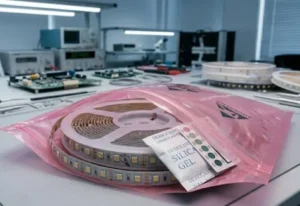
When we test strips on our production line before shipment, we power every reel at full brightness and inspect for dead segments. Even with automated SMD placement, a cold solder joint 5 or a micro-crack in the copper trace can slip through. In the field, these issues multiply because of bending, pulling, heat, and moisture.
Common Causes of Section-Level Failure
Here are the most frequent reasons we see for partial failure:
| Cause | What Happens | How to Identify |
|---|---|---|
| Cold or cracked solder joint | One LED group loses electrical contact | Gently flex the strip near the dead area; if it flickers, the joint is bad |
| Damaged copper trace | Circuit breaks at one point along the strip | Visually inspect the PCB for hairline cracks or dark spots |
| Faulty LED chip | One LED in a series group fails open | Dead group is always the same 3-LED section |
| Moisture ingress | Corrosion on pads or traces | Green or white residue visible on the PCB surface |
| Excessive bending | Trace fracture at a bend point | Dead section lines up with a tight bend radius in the installation |
What You Should Check First
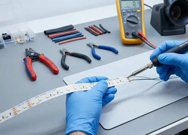
Before assuming the strip is defective, verify a few basics. Disconnect the strip and reconnect it to a known-good power supply. If the same section stays dark, the fault is in the strip itself. If the dead section moves or changes, the fault is likely in your connection or controller.
Use a multimeter set to DC voltage 6. Probe the pads at each end of the dead section. If you read full voltage on one side of the dead zone but zero on the other, you have found a break in the bus trace. If both sides show voltage but the LEDs are still dark, the fault is in that specific LED group — likely a bad chip or a joint on the resistor.
In our experience shipping to Australia and Germany, about 70% of "dead section" complaints trace back to installation damage — tight bends, staples through the PCB, or connectors that were not fully seated. Only a small percentage are actual manufacturing defects.
Can I fix a dead segment in my long-run LED strip without replacing the whole reel?
Long-run installations are where this question really matters. Our contractors in Germany often run 10 to 20 meters of strip in cove lighting. Replacing a full reel for one dead section is costly and wasteful.
Yes, you can fix a dead segment without replacing the whole reel. Cut the strip at the designated cut marks on either side of the faulty section, remove the dead piece, and reconnect the working sections using solderless connectors or by soldering short jumper wires.
Locate the Cut Lines
Every quality LED strip has marked cut points — usually indicated by a scissor icon or a copper pad between segments. You must cut only at these lines. Cutting between marks will damage the circuit and make the strip unusable at that point.
On our strips, cut marks appear every 50mm on 24V products and every 25mm on 12V products. This gives you fine control over exactly how much strip you remove.
Choose Your Reconnection Method
You have two main options for reconnecting the strip after removing the dead segment.
| Method | Skill Level | Reliability | Best For |
|---|---|---|---|
| Solderless clip connector | Beginner | Moderate — can loosen over time | Quick repairs, temporary fixes, accessible locations |
| Solder and jumper wire | Intermediate | High — permanent bond | Concealed installations, long-term projects, outdoor use |
Solderless connectors 7 are popular for DIY users. They clamp onto the exposed copper pads and make contact without heat. However, we have seen issues in the field where vibration or thermal cycling loosens the clip over months. For project-grade work, soldering is more dependable.
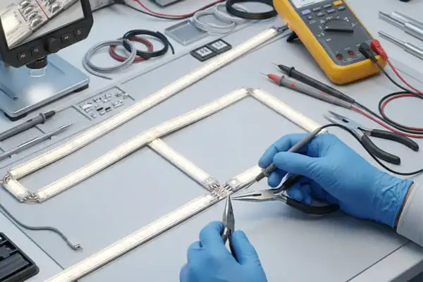
Step-by-Step Repair Process
- Disconnect power. Always work with the strip unplugged.
- Mark the dead segment. Identify the exact cut points on both sides.
- Cut cleanly. Use sharp scissors or a utility knife. Cut straight across the pads.
- Prepare the pads. If soldering, lightly tin the copper pads on both working ends.
- Connect. Use a short jumper wire (matching gauge) or a strip-to-strip connector. Match polarity — positive to positive, negative to negative. For RGBW strips, match all four or five channels.
- Test before securing. Power on and confirm the repaired area lights up.
- Seal the joint. Use heat-shrink tubing or silicone sealant for waterproof installations.
When Repair Is Not Worth It
If you find multiple dead segments across a reel, or if the dead sections reappear after repair, the problem is likely deeper — a defective batch, a failing power supply, or a trace-level issue across the board. In those cases, replacing the affected reel is more efficient than chasing multiple faults.
We always recommend keeping a small stock of matching strip on hand for any large project. When we ship orders, we can include spare segments for field repairs. This saves our partners time and avoids mismatches in color temperature or bin.
How do I troubleshoot voltage drop or connection issues causing dark spots in my installation?
When our Australian partners install 15-meter cove runs and notice the last two meters are noticeably dimmer, the culprit is almost always voltage drop 8. This is probably the most underestimated issue in LED strip installations.
Voltage drop occurs when the resistance of the copper traces reduces voltage along the length of the strip, causing LEDs at the far end to receive less power. Fix it by using shorter runs, powering from both ends, using a higher-voltage strip (24V or 48V), or placing the power supply centrally.
Understanding Voltage Drop in Practice
Every conductor has resistance. The thin copper traces on an LED strip are no exception. As current flows from the power supply end toward the far end, voltage decreases. The longer the run, the greater the drop.
A 12V strip might read 12.0V at the power injection point but only 10.5V at the far end of a 10-meter run. That 1.5V difference is enough to make the far LEDs visibly dimmer. On RGB strips, it can also cause color shift — warm whites may appear pinkish or yellowish at the tail.
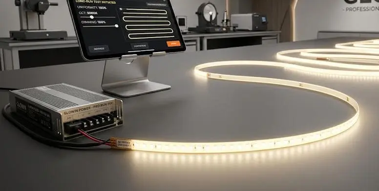
How to Measure Voltage Drop
Use a DC multimeter. Measure voltage at the power feed point, then at the midpoint, and finally at the far end. Record your readings.
| Measurement Point | Expected (24V Strip) | Concern Threshold |
|---|---|---|
| Power feed end | 24.0V | Below 23.5V — check supply |
| Midpoint (5m mark on a 10m run) | 23.2–23.8V | Below 22.5V — consider power injection |
| Far end (10m mark) | 22.5–23.5V | Below 21.5V — action required |
If your far-end voltage drops below about 90% of the rated voltage, you will see visible dimming and possible color inconsistency.
Solutions for Voltage Drop
Use 24V or 48V strips instead of 12V. Higher voltage means lower current for the same wattage, which reduces resistive losses along the traces. Our 48V constant-voltage strips are specifically designed for runs over 10 meters.
Power from both ends. Run a second wire from the power supply to the far end of the strip. This halves the effective run length and dramatically reduces drop.
Use a centrally placed power supply. Instead of feeding from one end, feed from the center so the maximum run length in either direction is halved.
Add power injection points. For very long runs, inject power at every 5-meter mark. This requires additional wiring but ensures uniform brightness.
Connection Issues That Mimic Voltage Drop
Sometimes what looks like voltage drop is actually a bad connection. A loose wire in a terminal block, a corroded connector, or a wire gauge that is too thin can all restrict current and cause the same symptoms.
Check every connection point with your multimeter. If you see a significant voltage difference across a single connector (for example, 24V going in and 22V coming out), that connector has high resistance and needs to be re-done. Clean the contact surfaces, use proper wire gauges, and tighten terminal screws firmly.
We always recommend using at least 18 AWG wire for runs under 5 meters and 16 AWG or thicker for longer runs. Thin wire is one of the most common mistakes we see in field installations.
What steps should I take if my project-grade LED strips show batch-to-batch failure or color inconsistency?
This is the question that keeps project managers up at night. When we ship a second batch of LED strip for the same hotel lobby project and the color does not match the first batch, nobody is happy. Our QC process exists specifically to prevent this.
If you experience batch-to-batch inconsistency, request LED bin codes and color tolerance data from your supplier, compare samples from both batches under identical conditions, and establish a supply agreement that locks in specific LED bins and CCT tolerances for the life of the project.
Why Batch Variation Happens
LED chips are manufactured in large wafers and then sorted — or "binned" — by color temperature, brightness, and forward voltage. Even within the same product line, different production runs may pull from different bins. If a supplier does not control binning tightly, two reels of "3000K warm white" could look noticeably different side by side.
This is not just a theoretical concern. We had a case where a distributor in Germany received two shipments three months apart. Both were labeled 3000K, but the second batch measured at 3150K. Installed in the same corridor, the difference was visible to the naked eye. We traced the issue to a chip supplier who had shifted bins between orders. Since then, we lock LED bin codes for every ongoing project.
How to Evaluate and Prevent Color Inconsistency
| Factor | What to Ask Your Supplier | Why It Matters |
|---|---|---|
| LED bin code | Can you provide the exact MacAdam ellipse step 9 and bin number? | Tighter binning (3-step or less) means less visible color variation |
| CCT tolerance | What is the +/- Kelvin tolerance per reel? | A ±100K tolerance is much tighter than ±300K |
| CRI consistency | Is CRI tested per batch or per reel? | CRI shifts can cause visible differences even at matched CCT |
| Aging and burn-in | Are strips burned in before shipping? | Initial brightness and color settle after the first few hours of use |
| Sample matching | Can I get pre-production samples from the same bin? | Allows you to verify match before committing to a full order |
Steps to Take When You Notice the Problem
- Document the issue. Photograph both batches installed side by side under the same lighting conditions. Note the reel numbers, batch dates, and any labels.
- Measure with a spectrometer or colorimeter. If possible, get CCT and CRI readings from both batches. This gives you objective data for a conversation with your supplier.
- Contact your supplier with data. Share your findings and ask for the bin codes of both batches. A responsible supplier will have this information on file.
- Request replacement from the same bin. If the second batch is out of spec, ask for a replacement matched to the first batch.
- Establish a bin-lock agreement. For any ongoing or phased project, agree in writing on the specific bin codes, CCT range, and CRI minimum. This prevents future mismatches.
Addressing Batch-Level Failures
If an entire batch shows higher-than-expected failure rates — dead LEDs, flickering, or premature dimming — the root cause is usually in the components or the manufacturing process. Common culprits include:
- Substandard LED chips from a secondary supplier
- Insufficient solder paste during reflow
- Poor-quality resistors that drift under thermal stress
- Inadequate conformal coating on waterproof strips, allowing moisture entry
When we detect a quality anomaly on our line, we quarantine the batch, trace every component to its lot number, and run accelerated aging tests 10 before releasing any product. We encourage our partners to request test reports and to sample-test each incoming batch before deploying it on a job site.
If you are a distributor or contractor receiving strips from any supplier, keep a reference reel from your first accepted batch. Use it as a visual and measured baseline for every subsequent delivery. This simple practice catches problems before they reach the installation site.
Conclusion
Troubleshooting LED strip failures follows a clear path: check power first, inspect connections second, and isolate the faulty section last. For project-grade work, prevent problems with proper voltage planning, bin-locked sourcing, and spare stock.
Footnotes
- Explains voltage compatibility and calculation for LED strip power supplies. ↩︎
- Explains characteristics of good solder joints and common types in electronics. ↩︎
- Explains how LED strips are internally wired in series-parallel groups for functionality. ↩︎
- Explains the purpose of a current-limiting resistor in protecting LEDs from excessive current. ↩︎
- Defines cold solder joints and lists common causes like insufficient heat or movement during cooling. ↩︎
- Provides a step-by-step guide on how to safely and accurately measure DC voltage with a multimeter. ↩︎
- Compares solderless and soldered connectors, highlighting reliability concerns with solderless options. ↩︎
- Explains voltage drop in LED strips, its causes, and its impact on brightness and color consistency. ↩︎
- Explains MacAdam ellipses as a measure of LED color consistency and their practical significance in lighting. ↩︎
- Defines accelerated reliability testing and its importance in assessing product longevity and identifying flaws in electronics. ↩︎