
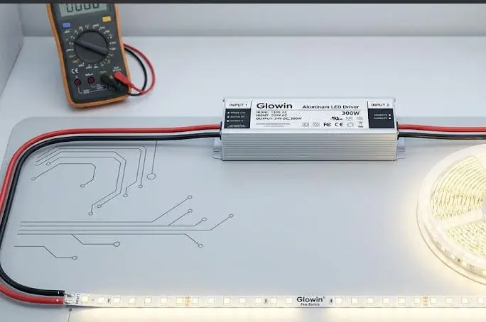
Когда наша производственная команда занимается заказами на пользовательские светодиодные ленты, требующими точной резки и пайки на заводском уровне — и самые распространённые жалобы в полевых условиях, которые мы слышим от подрядчиков, связаны с одной вещью: неправильной резкой или холодный пай 1 выполненной на месте.
Чтобы правильно разрезать и припаять светодиодные ленты, необходимо разрезать только по обозначенным производителем линиям разреза на медных площадках, предварительно припаяйте оба конца проводов и площадки, быстро припаять провода с правильной полярностью, а затем проверить соединение перед герметизацией или постоянной установкой ленты.
Это руководство проведёт вас через каждый шаг, от поиска правильной точки реза до герметизации водонепроницаемых соединений. Будь вы подрядчиком, работающим над коммерческой отделкой, или дистрибьютором, советующим своим монтажным клиентам, нижеописанные детали помогут вам избежать мёртвых сегментов, мерцания и неудачных уличных установок. Начнем с самого реза.
Где находятся точные точки реза на моих светодиодных лентах высокой плотности?
Один вопрос, на который наша команда технической поддержки отвечает почти ежедневно, — это где именно делать рез на высокоплотной ленте — потому что при большем количестве светодиодов на метр метки реза расположены ближе друг к другу и их легче пропустить. светодиодные ленты высокой плотности 2
Точки реза на светодиодных лентах всегда расположены на медных пайковых площадках, обычно обозначенных иконкой ножниц, пунктирной линией или штриховой линией. Резать в любом другом месте — значит разорвать цепь для этого сегмента, что приведет к мертвым светодиодам, которые невозможно исправить без полного удаления поврежденного участка.
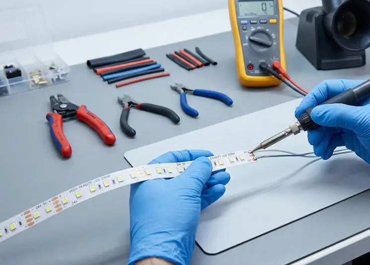
Как определить линию реза
Каждая светодиодная лента построена из повторяющихся электрических сегментов 3. Каждый сегмент содержит определённое количество светодиодов и их соответствующих резисторов. Линия реза расположена между двумя сегментами, прямо через середину открытых медных площадок. На стандартной 12V одноцветной ленте эти площадки обычно появляются каждые три светодиода. На 24V ленте — каждые шесть светодиодов. Ленты высокой плотности с 120 или 240 светодиодами на метр также следуют этому правилу — интервалы реза просто расположены ближе друг к другу.
Обратите внимание на эти визуальные подсказки:
- Маленькая иконка ножниц напечатанная на поверхности ленты.
- A пунктирная или штриховая линия проходящая по ширине ленты.
- Обнажённые медные площадки которые немного шире, чем дорожки, соединяющие светодиоды.
Если вы не видите метки, аккуратно протрите поверхность сухой тканью. На силиконовых или смоляных водонепроницаемых полосках метки могут быть видны сквозь покрытие или напечатаны на обратной стороне.
Интервал резки по типу полоски
| Тип полосы | Напряжение | Типичный интервал резки | Количество медных площадок в точке резки |
|---|---|---|---|
| Одноцветный (SMD 2835 4) | 12 В | Каждые 3 светодиода (~25 мм при 120 светодиодах/м) | 2 площадки (+ и −) |
| Одноцветный (SMD 2835) | 24В | Каждые 6 светодиодов (~50 мм при 120 светодиодах/м) | 2 площадки (+ и −) |
| RGB (SMD 5050) 5 | 12 В | Каждые 3 светодиода (~50 мм при 60 светодиодах/м) | 4 площадки (R, G, B, +) |
| RGBW (SMD 5050) | 24В | Каждые 6 светодиодов (~100 мм при 60 светодиодах/м) | 5 площадок (R, G, B, W, +) |
| Tunable White | 24В | Каждые 6 светодиодов | 3 площадки (+, теплый, холодный) |
| Адресуемый (WS2812B) 6 | 5V | Каждая 1 светодиод | 3 контакта (VCC, Data, GND) |
Общие ошибки при резке
Самая распространенная ошибка, которую мы видим на месте, — это резка между медными контактами, а не через них. Это оставляет на поверхности не пайляемую область на одной или обеих сторонах разреза, что делает повторное подключение практически невозможным. Еще одна ошибка — резка под углом, что может разорвать трассу с одной стороны, оставив другую целой. Всегда используйте острые ножницы или прецизионные кусачки и режьте прямо по полоске.
Перед тем как резать, измерьте дважды. Подтвердите нужную длину, найдите ближайшую метку для резки и убедитесь, что полоска плоская и стабильная. Сначала отключите полоску от всех источников питания. Это защитит вас и предотвратит случайные короткие замыкания, которые могут повредить драйвер или саму полоску.
Еще одно важное замечание: на адресных полосках, таких как WS2812B, каждый светодиод управляется отдельно. Можно резать в каждом отдельном светодиоде. Но резка влияет на адресацию — если вы удалите средний участок и снова соедините, возможно, потребуется перепрограммировать контроллер для учета нового количества пикселей.
Как припаять светодиодные ленты, чтобы обеспечить надёжное соединение для моей коммерческой установки?
Когда мы отправляем заказные светодиодные полоски подрядчикам в России, мы всегда включаем в комплект руководство по пайке — потому что даже опытные электрики иногда недооценивают, насколько сильно отличается Пайка на плате 7 от стандартной работы с проводами.
Чтобы надежно припаять светодиодные ленты, сначала предварительно припаяйте медные площадки на ленте и оголенные концы проводов. Затем поместите припаянный провод на припаянную площадку, нажмите паяльником на оба примерно на две секунды, пока припой не растечется, и держите провод неподвижным, пока соединение не остынет и не затвердеет.
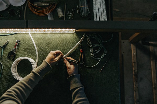
Инструменты и материалы, которые вам понадобятся
Перед началом соберите все. Отсутствие инструмента в процессе пайки может привести к тому, что вы будете держать горячий паяльник слишком долго на контакте и повредите полоску.
| Инструмент / Материал | Рекомендуемые характеристики | Цель |
|---|---|---|
| Паяльник | 25–60 Вт, тонкий конический наконечник | Нагревательные пластыри и проволока для пайки |
| Паяльник с канифолью 8 | Оловянно-свинцовый или бессвинцовый сплав 60/40, 0.8 мм | Обеспечивает присадочный металл для соединения |
| Многожильный провод | 20–22 AWG (один цвет), 20 AWG (RGB) | Соединяет сегменты ленты или удлиняет цепи |
| Кусачки для снятия изоляции | Соответствующий размер AWG | Чисто снимает изоляцию |
| Изопропиловый спирт | Концентрация 90%+ | Очищает пластины перед припоем |
| Помогающие руки / зажим | Любой стиль с регулируемыми рукоятками | Держит ленту и провод устойчиво |
| Термоусадочная трубка 9 | Клеевая внутренняя оболочка, размер по размеру ленты | Защищает готовое соединение |
| Карандаш для флюса (по желанию) | На основе канифоли | Улучшает плавление припоя на окисленных площадках |
Пошаговый процесс пайки
Шаг 1: Отключите питание. Полностью отсоедините ленту от источника питания. Никогда не паяйте подключенную ленту.
Шаг 2: Закрепите ленту. Используйте держатель или приклейте ленту к рабочей поверхности, чтобы она не двигалась. Медные площадки должны быть обращены вверх и быть чистыми. Если есть остатки, протрите площадки изопропиловым спиртом и дайте им высохнуть.
Шаг 3: Зачистите и залудите провода. Зачистите около 3–4 мм изоляции с каждого конца провода. Нанесите небольшое количество припоя на каждый оголенный конец провода, одновременно касаясь провода паяльником и припоем. Провод должен впитать припой и выглядеть блестящим. Это называется предварительной лужением.
Шаг 4: Залудите площадки. Прикоснитесь кончиком паяльника к каждой медной площадке на ленте и подайте небольшое количество припоя на площадку. На каждой площадке должен образоваться тонкий, блестящий купол припоя. Время контакта с паяльником должно быть менее двух секунд, чтобы избежать теплового повреждения светодиодов или печатной платы.
Шаг 5: Соедините провод с площадкой. Поместите залуженный конец провода поверх залуженной площадки. Одновременно прижмите паяльник к проводу и площадке. Предварительно нанесенный припой на обеих поверхностях расплавится и соединится. Это должно занять около одной-двух секунд. Уберите паяльник.
Шаг 6: Держите неподвижно. Не двигайте провод до полного остывания и затвердевания припоя. Движение провода во время охлаждения создает "холодный шов" — тусклое, шероховатое соединение, которое механически слабое и электрически ненадежное.
Шаг 7: Осмотрите. Хорошее соединение выглядит блестящим и гладким. Плохое соединение выглядит тусклым, зернистым или шарообразным. Если соединение выглядит плохо, кратковременно нагрейте его и добавьте крошечное количество свежего припоя.
Соответствие количества проводов типу ленты
Этот шаг имеет решающее значение. Если вы подключите неправильный провод к неправильной площадке, лента не будет работать — или, что хуже, вы можете повредить светодиоды или контроллер.
- Одноцветные ленты: Два провода. Красный к положительной площадке (+), черный к отрицательной площадке (−).
- RGB-ленты: Четыре провода. Один для каждого цветового канала (Красный, Зеленый, Синий) и один общий положительный (+).
- RGBW-ленты: Пять проводов. Те же, что и RGB, плюс выделенный белый канал.
- Регулируемые белые ленты: Три провода. Положительный, теплый белый и холодный белый.
Всегда дважды проверяйте маркировку на плате, напечатанную на ленте, перед пайкой. Они маленькие, но читаемые.
Почему предварительное припоивание так важно
Предварительное припоивание не является опцией при работе с LED-лентами. Без него вам придется держать паяльник на плате гораздо дольше, пока вы подаете припой, расплавляете его и позиционируете провод — все одновременно. Это дополнительное время передает больше тепла на ленту. Светодиодные чипы и клеящая основа чувствительны к теплу. Наши инженеры рекомендуют держать контакт паяльника с платой не более трех секунд на каждую. Предварительное припоивание делает это возможным, потому что окончательное соединение требует только быстрого повторного прогрева, а не полного расплавления и подачи припоя.
Как можно заново герметизировать водонепроницаемые светодиодные ленты после их обрезки, чтобы сохранить степень защиты IP?
Наши IP65 и IP67-ленты 10 поставляются с заводскими герметичными силиконовыми оболочками, но как только подрядчик обрезает или припаивает их на месте, герметичность нарушается — и если проект находится на улице или в влажной среде, открытое соединение — это потенциальная причина отказа установки.
После обрезки и пайки водонепроницаемых LED-лент необходимо повторно герметизировать открытое соединение, надев совместимый силиконовый заглушку или термоусадочную трубку, а затем нанести водонепроницаемый силиконовый герметик вокруг соединения и дать ему полностью застыть перед включением питания или воздействием влаги.
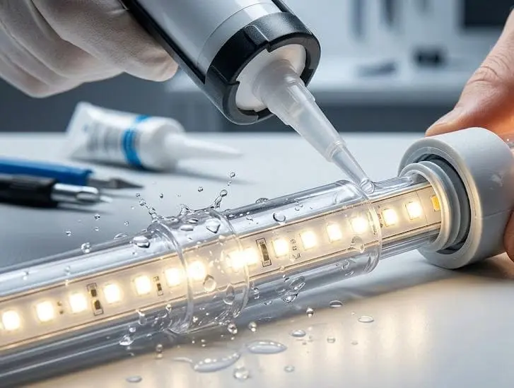
Открытие водонепроницаемой оболочки
Перед тем как паять водонепроницаемую ленту, необходимо получить доступ к медным платам. На силиконовых лентах с защитой IP67 аккуратно разрежьте оболочку вдоль по длине в месте пайки острым канцелярским ножом. Аккуратно отогните немного силикона, чтобы открыть плату — обычно 10–15 мм. На силиконовых лентах с покрытием IP65 используйте нож, чтобы аккуратно соскоблить покрытие с области платы. Не царапайте плату. Не торопитесь. Спешка в этом шаге может повредить медную дорожку и испортить соединение еще до начала пайки.
Процесс повторной герметизации
После того как вы выполните пайку и протестируете соединение (всегда проверяйте перед герметизацией), выполните следующие шаги:
Насуйте силиконовую заглушку или термоусадочную трубку на соединение. Многие производители — включая нас — поставляют заглушки, соответствующие поперечному сечению ленты. Если вы используете термоусадочную трубку с клеевым слоем, убедитесь, что она предназначена для уличного использования и подходит по размеру, чтобы плотно охватывать ленту и кабельный пучок.
Нанесите силиконовый герметик. Заполните внутреннюю часть заглушки или зазор между термоусадочной трубкой и лентой нейтральным силиконовым герметиком. Избегайте силиконового герметика с уксусной кислотой (тот, что пахнет уксусом), так как он со временем может окислить медь.
Сдавите и затвердевайте. Плотно прижмите заглушку к ленте, чтобы герметик заполнил все зазоры. Дайте герметику затвердеть в течение времени, указанного на тюбике — обычно 12–24 часа.
Проверьте. После затвердевания аккуратно согните соединение. Если вы заметите зазоры или герметик оторвался, нанесите второй слой.
Рассмотрение уровня защиты IP
Важно понимать, что соединение, выполненное в полевых условиях, редко соответствует заводскому уровню защиты IP. Заводская лента с IP67 проходит контролируемое формование и затвердевание. Полевая герметизация зависит от техники монтажника. Тем не менее, правильно повторно герметизированное соединение может обеспечить эффективную водонепроницаемость для большинства коммерческих применений, таких как фасады зданий, ландшафтное освещение и крытые уличные потолки.
Для полностью погружных применений (IP68) мы настоятельно рекомендуем заказывать ленты, предварительно нарезанные и припаянные на заводе под вашу точную длину, чтобы не было необходимости в полевых резках.
Расслабление напряжения — не опция
После герметизации добавьте устройство для снятия напряжения. Небольшой кусочек горячего клея или зажим для кабеля рядом с соединением предотвращает натяжение провода на паяльную площадку. В уличных установках тепловое расширение и вибрации ветра со временем создают нагрузку на любое незащищенное соединение. Устройство для снятия напряжения поглощает это движение, чтобы пайка не испытывала нагрузки.
Как лучше всего паять длинные светодиодные ленты, чтобы избежать падения напряжения?
Длинные светодиодные ленты являются основной частью нашей продуктовой линейки, и самой большой технической проблемой, с которой сталкиваются наши клиенты при проектах длиной более 10 метров, является падение напряжения — светодиоды на дальнем конце ленты выглядят тусклее и иногда меняют цветовую температуру, потому что недостаточно напряжения достигает их.
Чтобы избежать падения напряжения на длинных участках светодиодных лент, используйте более толстый провод (16–18 AWG) для подачи питания, припаивайте дополнительные точки питания через равные промежутки вдоль ленты и поддерживайте чистоту и низкое сопротивление пайки, чтобы они не увеличивали совокупные потери напряжения по длине.

Почему происходит падение напряжения
Светодиодные ленты по сути представляют собой длинные тонкие печатные платы с узкими медными дорожками. Когда через эти дорожки протекает ток, сопротивление вызывает падение напряжения по длине. Чем дальше от источника питания, тем ниже напряжение на каждом светодиоде. На ленте 12 В падение всего в 1–2 вольта может привести к тому, что светодиоды в конце будут выглядеть тусклее или с измененной цветовой температурой. На лентах 24 В эффект снижен, потому что при той же мощности ток в два раза меньше, что вызывает меньшие сопротивления — но это все равно происходит на длинных участках.
Объяснение подачи питания
Подача питания означает добавление дополнительных проводов питания в точки вдоль ленты, чтобы восполнить напряжение. Вместо питания ленты только с одного конца, вы протягиваете параллельный провод от источника питания к середине и дальнему концу ленты. Это обеспечивает почти полное напряжение для каждого участка.
Вот как это работает на практике:
- Определите точки подачи питания. Для 20-метровой ленты на 24 В вы можете подавать питание в 0 м, 10 м и 20 м.
- Протяните провод от источника питания к каждой точке подачи. Используйте многожильный провод 16–18 AWG для длинных участков дома.
- На каждой точке подачи припаяйте провода питания напрямую к положительным и отрицательным контактам ленты.
Выбор сечения провода для длинных участков
| Общая длина участка (лента 24 В) | Рекомендуемое сечение провода для подачи питания | Количество точек подачи |
|---|---|---|
| До 5 м | 20–22 AWG | 1 (только в начале) |
| 5–10 м | 18–20 AWG | 1–2 |
| 10–20 м | 16–18 AWG | 2–3 |
| Более 20 м | 14–16 AWG | 3+ (консультация инженера) |
Это общие рекомендации. Точный диаметр провода зависит от мощности полосы на метр и расстояния от источника питания до точки инъекции. Наша команда может рассчитать конкретные требования для любого проекта — просто отправьте нам схему.
Качество пайки влияет и на падение напряжения
Плохое соединение пайки увеличивает сопротивление. В одном соединении это может быть незначительно. Но при длинной линии с несколькими пайками — углами, соединениями сегментов, точками инъекции питания — суммарное сопротивление увеличивается. Каждое соединение должно быть гладким, блестящим и полностью спаянным. Повторно прогрейте тусклые или комковатые соединения. Используйте флюс, если контакты окислены.
Также избегайте использования чрезмерно тонкого провода между сегментами полосы. Некоторые монтажники используют перемычки 24 AWG или даже 26 AWG для соединения углов. Такой провод становится узким местом для тока, особенно если полоса потребляет более нескольких ватт на метр. Подбирайте диаметр перемычки в соответствии с током полосы, а не тем, что удобно разместить за алюминиевым каналом.
Пайка vs. безпаяные соединители для длинных линий
Безпаяные защелкивающиеся соединители удобны. Они защелкиваются на медные контакты и создают соединение без нагрева. Но при длинных коммерческих линиях они создают больше сопротивления, чем пайка, и могут ослабнуть со временем из-за теплового цикла. Для проектов, где важна надежность и визуальная однородность — гостиницы, розничная торговля, архитектура — рекомендуется паять каждое соединение. Соединители подходят для быстрых прототипов, временных дисплеев или коротких жилых линий, где легко получить доступ для повторной работы.
Проверьте перед герметизацией
После пайки всех соединений и точек инъекции питания включите полосу и пройдитесь по всей длине. Обратите внимание на:
- Любые темные сегменты (указывает на пропущенное или сломанное соединение).
- Затемнение на конце (указывает на падение напряжения — добавьте еще одну точку инъекции).
- Изменение цвета (от теплого к холодному или наоборот — также симптом падения напряжения на регулируемых или RGB-полосах).
- Мерцание (указывает на холодное соединение или ослабленный провод).
Исправьте любые проблемы сейчас. После монтажа полосы в канал, покрытия диффузором и герметизации повторная работа становится очень дорогой и трудоемкой.
Заключение
Правильная резка и пайка — основа каждой надежной установки LED-полос. Режьте по отмеченным контактам, припаивайте все, быстро паяйте, проверяйте перед герметизацией и инжектируйте питание на длинных линиях. Правильное выполнение этих основ обеспечит яркую и безотказную работу ваших установок на годы.
Примечания
- Заменена ссылка 404 на авторитетную статью, объясняющую холодные пайки. ↩︎
- Определяет светодиодные ленты высокой плотности и их преимущества для равномерной световой отдачи. ↩︎
- Обсуждает, как состоят светодиодные ленты из сегментов и как сопротивление влияет на них. ↩︎
- Предоставляет характеристики и детали типа светодиодного чипа SMD 2835. ↩︎
- Объясняет значение и характеристики RGB SMD 5050 светодиодных чипов. ↩︎
- Предлагает технический паспорт и сведения о применении адресуемого светодиода WS2812B. ↩︎
- Освещает основные техники пайки печатных плат, инструменты и распространённые ошибки. ↩︎
- Подробно описывает преимущества и правильное использование флюсовой припойной пасты в электронике. ↩︎
- Описывает назначение, применение и преимущества термоусадочной трубки для изоляции. ↩︎
- Сравнивает рейтинги IP65 и IP67, объясняя их уровни защиты от воды и пыли. ↩︎

 English
 Spanish
 German
 Russian
 Arabic
 French
 Portuguese