When we develop new high-density COB (Chip-on-Board) strips, we often face a critical challenge: the very design that makes COB strips beautiful—that seamless, dotless line of light,also makes them mechanically vulnerable. Unlike traditional SMD strips where the chip has "breathing room," COB chips are densely packed and encapsulated directly on the PCB. If we do not rigorously test for thermal expansion and contraction, a project installed in the fluctuating temperatures of Melbourne or Berlin can fail within months. The silicone phosphor layer expands at a different rate than the copper PCB, creating internal stress that can snap wire bonds or crack solder joints.
To ensure reliability, you must execute a three-step protocol: thermal cycling between -20°C and +60°C with two-hour dwell times, followed by continuous high-temperature operation for 12 hours, and a final physical inspection. This process exposes structural weaknesses like solder cracks, phosphor delamination, and PCB warping caused by thermal expansion mismatches.
Reliability isn't just about whether the light turns on; it is about structural integrity over time. Once you understand the baseline testing requirements, you can prevent costly site replacements and warranty claims.
What specific standards should I use for thermal shock testing of COB LED strips?
In our experience exporting to strict markets like Germany, relying solely on generic datasheet promises is a recipe for disaster. We have seen competitors' products pass basic electrical tests but fail catastrophically when subjected to the rapid temperature shifts found in outdoor architectural applications. The standards you choose act as the roadmap for your testing protocol.
Adhere to IEC 60068-2-14 for environmental testing to simulate rapid temperature changes and IESNA LM-80 for long-term lumen maintenance. Additionally, apply internal protocols for "Cold Start" surge testing to ensure bond-wire integrity, as standard certifications often miss the specific mechanical stresses unique to high-density COB architectures.
Understanding the Framework of Reliability Standards
When we sit down with our engineering team to define a test plan, we don't just pick random temperatures. We align our internal benchmarks with international standards, but we often find we need to exceed them for COB technology. The high density of chips (often 480 or 512 chips per meter) creates a unique thermal footprint that standard SMD tests might miss.
The primary standard we look to is IEC 60068-2-14, which governs temperature cycling. This standard defines how fast the temperature should change and how long the product must "soak" at the extremes. However, for COB strips, the IESNA LM-80 standard is equally critical, though it focuses on lumen maintenance (how much brightness is lost over time). The challenge with COB is that physical degradation (cracking) often happens before the light output naturally fades.
Critical Standards Comparison
We have compiled a breakdown of the standards we utilize and how we adapt them for high-density strips:
| Standard | Primary Focus | Application for COB Strips | Our Internal Adjustment |
|---|---|---|---|
| IEC 60068-2-14 | Thermal Cycling / Shock | Tests the mechanical bond between the silicone encapsulation and the PCB. | We increase the ramp rate (speed of temp change) to simulate harsher outdoor transitions. |
| IESNA LM-80 | Lumen Maintenance | Measures how heat degrades the phosphor and chip brightness over time. | We combine this with vibration testing to ensure the phosphor doesn't crack as it ages. |
| MIL-STD-810G | Environmental Engineering | Extreme stress testing for military or heavy industrial use. | Used only for our "Ruggedized" IP68 product lines destined for extreme climates. |
| Internal "Cold Start" | In-rush Current | Tests if the strip can survive powering up at -20°C when resistance is low. | Essential for COB, as the dense circuitry can surge and blow fuses at low temps. |
The Gap Between Standards and Reality
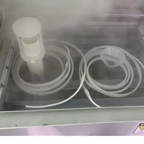
While standards are necessary, they are often written for general electronics or discrete LEDs. They don't always account for the continuous linear structure of a COB strip. For example, a standard might require a test on a 10cm segment. We have found that testing a full 5-meter reel is crucial because thermal expansion accumulates over length. A 10cm piece might not warp, but a 5-meter run installed in an aluminum profile certainly will.
We also apply a "Double 85" test (85°C at 85% Relative Humidity) specifically to check the adhesive backing. A common failure point isn't the LED itself, but the 3M tape delaminating from the heat sink, causing the strip to overheat and fail. Standards give you a pass/fail grade, but critical thinking about the application environment gives you a reliable product.
How many temperature cycles are required to prove the durability of my LED strips?
When we discuss longevity with our clients, the conversation often shifts from "hours of life" to "cycles of stress." A light that stays on 24/7 in a climate-controlled office faces very different stresses than a façade light that heats up and cools down every day and night. Determining the right number of cycles is a balance between catching "infant mortality" defects and simulating a full lifespan.
For basic quality control, run 5 to 10 cycles with two-hour dwell times to catch early manufacturing defects. However, for product validation and predicting long-term durability, perform 100 to 500 cycles combined with continuous power-on testing to simulate years of seasonal expansion and contraction stress.
The Three-Step Testing Protocol
Through years of refining our production process, we have established a three-step approach that effectively weeds out weak structures in COB strips. This is not just theory; it is the exact workflow our QC department follows.
Step 1: The Cold/Hot Cycle (Structural Stress)
This is the most aggressive phase. We set our chambers to cycle between -20°C and +60°C.
- Dwell Time: We keep the strips at each extreme for 2 hours. This ensures the entire mass of the strip (PCB, silicone, copper traces) reaches the target temperature.
- Cycle Count: For a standard production batch check, 5 to 10 cycles are sufficient. This triggers the "infant mortality" failures—weak solder joints will snap here. For a new product R&D validation, we push this to 100+ cycles.
Step 2: Continuous Power-On (Thermal Endurance)
After the cycling, the structure might be weakened but not broken. We then keep the strips in the high-temperature phase (+60°C to +85°C) and keep them lit for 8 to 12 hours.
- Why? Heat expands the materials. If there is a micro-crack in the copper trace, the expansion might force it open, breaking the circuit. This step catches intermittent failures that only appear when the lights are hot.
Step 3: Physical and Visual Inspection
The final step is a detailed check. We look for specific physical symptoms that indicate the materials are fighting each other.
Cycle Count vs. Reliability Confidence
How many cycles you run depends on what you are trying to prove. Here is how we categorize our testing intensity:
| Test Level | Cycle Count | Purpose | Typical Failure Found |
|---|---|---|---|
| Production Screening | 5 - 10 Cycles | Quick QC before shipping. | Cold solder joints, major PCB defects. |
| Design Validation | 50 - 100 Cycles | Approving a new material supplier. | Adhesive failure, silicone yellowing. |
| Lifespan Simulation | 200 - 500 Cycles | Simulating 5-10 years of outdoor use. | Phosphor cracking, copper fatigue, permanent lumen drop. |
| Destructive Testing | 1000+ Cycles | Finding the absolute breaking point. | Total delamination, FPC fracture. |
The "Bathtub Curve" Logic
We apply the logic of the "Bathtub Curve" to our decision-making. Failures tend to happen very early (manufacturing defects) or very late (wear and tear). The middle period is usually stable. By running the first 10-20 cycles, we are essentially fast-forwarding past the early failure stage. If a COB strip survives the rapid expansion and contraction of the first 10 cycles without the phosphor layer bubbling or the copper cracking, the statistical probability of it lasting its warranty period increases dramatically.
What equipment is essential for conducting reliable thermal stress tests in-house?
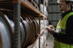
Setting up a testing lab can seem daunting, but for us, it was a necessary investment to guarantee the quality of our project-grade strips. You cannot rely on the raw material supplier's data alone; the assembly process changes the physics of the product. If you are a distributor or a large contractor considering in-house verification, you need specific tools to uncover the invisible defects in COB technology.
Essential equipment includes a programmable environmental chamber for precise temperature ramping, an integrating sphere for measuring lumen depreciation and color shift, and high-precision multimeters. You also need microscopes to inspect for micro-cracks in the solder joints and phosphor layer that are invisible to the naked eye.
The Core Testing Hardware
To replicate the tests we conduct, you need equipment that can control the environment and measure the results accurately.
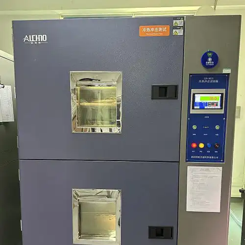
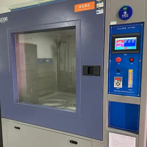
Programmable Environmental Chamber
This is the workhorse of reliability testing. You need a chamber capable of:
- Temperature Range: At least -40°C to +100°C.
- Programmability: You must be able to set "ramping" profiles (e.g., go from -20°C to +60°C in 10 minutes) and "dwell" times.
- Humidity Control: Optional but recommended. Testing at 85% humidity helps identify if moisture can penetrate the silicone layer after it has been stressed by heat.
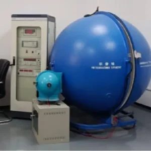
Integrating Sphere & Spectroradiometer
Thermal stress doesn't just break things; it changes them. We use an integrating sphere (like the Everfine HAAS-1200 system) to measure the light before and after the thermal cycles.
- What to watch: We look for CCT Drift. If a 3000K strip comes out of the oven reading 3200K or 2800K, the phosphor has been damaged.
DC Power Supply & Data Loggers
You need a power supply that can maintain constant voltage while recording current. A data logger is crucial because it can record the current draw during the temperature transition.
- The Insight: Often, a strip will flicker or drop current only during the transition from cold to hot. If you aren't logging data every second, you will miss this momentary failure.
Equipment Investment Tiers
Depending on your business model, you may not need a full factory lab. Here is a breakdown of equipment needs:
| Equipment | Function | Necessity Level | What it Detects |
|---|---|---|---|
| Environmental Chamber | Cycles Temp/Humidity | Critical | Structural failures, expansion issues. |
| Microscope (20x-50x) | Visual Inspection | Critical | Micro-cracks in phosphor, solder fractures. |
| DC Power Supply | Powers the strip | Critical | Voltage drop, current fluctuation. |
| Integrating Sphere | Optical Measurement | High | Color shift, lumen loss. |
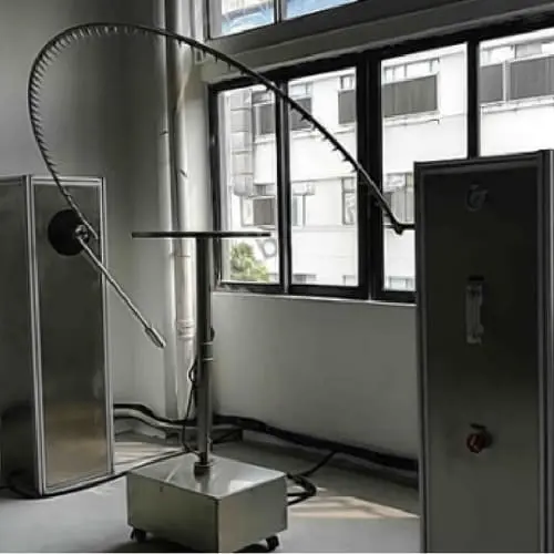
| Vibration Table | Mechanical Stress | Medium | Simulates transport or wind load. |
| Hi-Pot Tester | Electrical Safety | Medium | Insulation breakdown after thermal stress. |
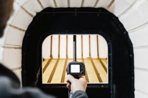
Why Visual Tools Matter for COB
We cannot stress enough the importance of the microscope. In traditional SMD strips, a cracked solder joint is often visible. In COB strips, the continuous phosphor layer hides the internal circuitry. After a thermal cycle, the strip might still light up, but a microscopic check might reveal that the copper foil has lifted slightly from the substrate (delamination). This is a ticking time bomb. We use digital microscopes to document the "before and after" state of the bond wires and the interface between the silicone and the PCB.
How do I identify potential failure points in high-density strips after thermal cycling?
The testing cycle is finished, and the chamber door opens. The strips might look fine at a glance, but the damage is often subtle. In our QC process, this is the most critical phase. We have to distinguish between cosmetic changes and functional failures. A slight yellowing might be acceptable, but a structural compromise is a rejection.
Identify failures by inspecting for local dark zones, phosphor bubbling, or PCB warping immediately after cycling. Electrically, check for increased resistance or voltage drop, while optically, measure for significant Color Temperature (CCT) drift, which indicates degradation of the silicone encapsulation or damage to the internal chip bonds.
Visual and Physical Inspection Criteria
The first thing our technicians look for is structural stability. Thermal expansion and contraction (CTE mismatch) is the enemy here. The silicone layer wants to expand at one rate, and the copper PCB at another.
1. Phosphor Layer Integrity
We look for bubbling or blistering. If the silicone has detached from the PCB, it creates an air gap. This air gap acts as an insulator, preventing heat from escaping the LED chip. This will lead to rapid burnout. We also check for cracking in the phosphor. Even a hairline crack can break the continuity of the light, creating a visible dark line.
2. PCB Warping and Delamination
Does the strip lie flat? If the copper foil has warped or curled, it means the adhesive bond between the copper and the substrate has failed. In high-voltage COB strips, this can be dangerous.
3. The "Dark Line" Phenomenon
We power on the strip and dim it to 10%. At full brightness, the glare can hide defects. At low light, we look for "dead sections" or areas that are dimmer than the rest. This usually indicates that a group of chips (a segment) has a fractured solder joint or a damaged resistor due to thermal stress.
Electrical and Optical Analysis
Visuals only tell half the story. We plug the strips into our analyzers to see what happened internally.
Electrical Resistance & Voltage Drop
We measure the voltage drop across the 5-meter reel again.
- The Red Flag: If the voltage drop has increased significantly compared to the pre-test measurement, it means the copper traces have been damaged/thinned by the stress, increasing resistance. This leads to more heat and a vicious cycle of failure.
Color Shift (CCT Drift)
We place the strip back in the integrating sphere.
- The Limit: We generally accept a shift of no more than ±150K for warm white.
- The Cause: If the shift is significant (e.g., >300K), it usually means the silicone phosphor mix has chemically degraded or "baked" during the high-temperature dwell time.
Failure Mode Analysis Table
Here is a guide to interpreting what you see after the test:
| Observation | Likely Cause | Severity | Action |
|---|---|---|---|
| Local Dark Section | Solder joint fracture or wire bond break. | Critical | Immediate Fail. Check soldering profile. |
| Bubbling under Silicone | Delamination due to CTE mismatch. | Critical | Immediate Fail. Check adhesive/silicone quality. |
| Yellowing of Strip | Silicone degradation from heat. | Major | Review silicone material quality. |
| Voltage Drop Increase | Micro-cracks in copper PCB traces. | Major | Review PCB thickness (2oz vs 3oz). |
| Adhesive Tape Peeling | Tape failure at high temp. | Minor/Major | Switch to high-temp VHB tape. |
The "Cold Start" Check
Finally, we perform a "Cold Start" test. We freeze the strip to -20°C and turn it on instantly at full power. In COB strips, the internal resistance drops at low temperatures, which can cause a massive in-rush of current. If the bond wires are weak from the thermal cycling, they will blow like a fuse right at this moment. This is a crucial test for outdoor reliability that many labs overlook.
Conclusion
Testing the reliability of high-density COB LED strips requires more than just leaving them on for a few hours. By implementing a rigorous thermal cycling protocol—specifically cycling between -20°C and +60°C, monitoring for CCT drift, and inspecting for structural delamination—we ensure that the sleek, dotless light our clients love can withstand the harsh realities of the physical world. Reliability is not an accident; it is engineered.