We see many project delays caused by vague length specifications. Misaligned COB strips in aluminum profiles can ruin the seamless dotless effect you paid for, turning a premium installation into a maintenance nightmare.
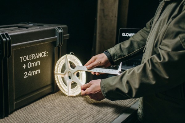
To confirm tolerances, you must specify a numerical range in your contract, such as +0mm/-4mm, rather than relying on "industry standards." Verify the strip's cutting increment—typically 25mm or 50mm—and require the supplier to account for end-cap thickness and potential reflow shrinkage in the final total length.
Before you finalize your next bulk order, you need to understand the technical constraints that dictate these lengths.
What is the standard cutting increment for high-density COB strips?
When we design PCB layouts for high-density strips, the circuit structure dictates where cuts are safe. Ignoring these fixed points destroys the circuit loop, leading to dead sections that our QC team works hard to prevent.
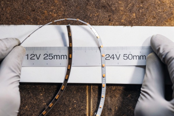
Standard cutting increments are generally 25mm for 12V strips and 50mm for 24V models due to the number of LEDs in series. However, new "cut-anywhere" COB technologies are emerging in 2025 that eliminate fixed points, offering greater flexibility for precise joinery without dark spots.
Understanding the Circuitry Behind the Cut
The "cutting increment" is not an arbitrary suggestion; it is the physical length of one complete electrical circuit unit on the Flexible Printed Circuit (FPC) board. If you cut anywhere else, you sever the copper path connecting the positive and negative rails to the LED chips, resulting in a section that will not light up.
For high-density COB (Chip on Board) strips, this unit length is determined by the voltage and the LED grouping.
- 12V Systems: Typically group 3 LEDs in series. Because the voltage drop across 3 chips matches the input, the circuit loop is short. This usually results in a cutting unit of 25mm. This shorter increment makes 12V strips ideal for intricate joinery or small cabinets where precision is key.
- 24V Systems: Typically group 6 or 7 LEDs in series. This requires a longer physical distance to accommodate the chips and resistors (or constant current ICs). Consequently, the cutting unit is often 50mm (roughly 2 inches). While 24V is better for long runs due to lower voltage drop, it is less flexible for precise fitting in short profiles.
The "Cut-Anywhere" Innovation
As we move into 2025, we are seeing a shift in manufacturing capabilities. New "Free Cut" or "Cut-Anywhere" COB strips are entering the market. These designs use a unique circuit matrix that allows the strip to be cut at any point without damaging the functionality of the remaining LEDs.
While these are currently more expensive to produce, they solve the headache of trying to match a 50mm grid to a 1237mm cabinet shelf. However, for the vast majority of standard projects, you are still bound by the fixed increments.
Visual Markers and Risks
On our production line, we print clear indicators on the FPC to guide installation. You will typically see:
- Scissor Icons: Printed in black silk screen.
- Copper Pads: Exposed oval or round copper areas where the cut must happen. These pads are also where you solder wires.
- Dotted Lines: On some dotless COB models, the phosphor gel covers the board entirely. In these cases, we mark the side of the PCB or use a translucent gel that allows the copper pads to shadow through.
Voltage vs. Cutting Precision
| Feature | 12V COB Strip | 24V COB Strip | "Cut-Anywhere" COB |
|---|---|---|---|
| Standard Cut Unit | 25mm | 50mm | Any length (approx. 1mm) |
| Precision Level | High | Medium | Ultra-High |
| Best Application | Small joinery, shelves, tight corners | Long linear runs, ceiling coves | Bespoke furniture, irregular shapes |
| Voltage Drop Risk | High (max run ~5m) | Low (max run ~10m) | Varies by design |
| Cost | Standard | Standard | Premium |
If you force a cut in the wrong place, you don't just lose the last few millimeters of light; you lose the entire preceding unit (25mm or 50mm), creating a significant dark spot at the end of your profile.
How do I negotiate tighter length tolerances for pre-cut project orders?
Our export team frequently handles requests for precise pre-cuts to save contractors labor costs. However, "exact length" is a physical impossibility without defined margins, and misunderstandings here cause the most friction.
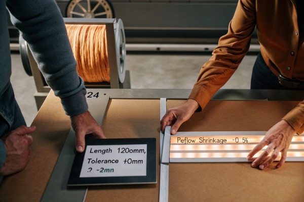
Negotiate a "negative tolerance" policy, such as +0mm/-2mm, ensuring strips fit inside profiles without buckling. Demand that the supplier accounts for PCB reflow shrinkage, which can shorten strips by 0.5% after heating, and leverage high-volume orders to request automated machine cutting for consistent precision.
The Strategy of Negative Tolerance
In construction and joinery, a strip that is 1mm too short is usually acceptable; a strip that is 1mm too long is a disaster. If the LED strip is longer than the aluminum channel, it cannot lay flat. It will ripple or buckle, causing the adhesive tape to fail and creating uneven "hot spots" where the strip presses against the diffuser.
When negotiating with us or any supplier, do not ask for "±1mm." Instead, specify a Negative Tolerance.
- Bad Spec: "Length: 1000mm ±2mm" (This allows 1002mm, which might not fit).
- Good Spec: "Length: 1000mm, Tolerance: +0mm / -4mm."
This tells the factory that under no circumstances can the strip exceed the target length. We would rather cut it slightly shorter to ensure it fits.
Accounting for Reflow Shrinkage
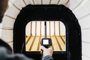
This is a technical detail few buyers know. During manufacturing, the FPC board goes through a reflow oven at temperatures exceeding 240°C to solder the LED chips. This heat causes the copper and polyimide materials to shrink slightly.
On a 5-meter reel, this shrinkage is negligible. But if you order 10,000 pieces of pre-cut 500mm strips, and we cut them based on the raw PCB design file before shrinkage, they might all arrive 1-2mm short.
- Actionable Tip: Ask your supplier: "Do you calibrate your cutting machines to account for post-reflow shrinkage?"
Volume Leverage for Automated Cutting
For small orders, workers often cut strips by hand using scissors. This introduces human error. The cut might be slanted, or they might miss the center of the copper pad.
For large project orders (e.g., >1000 meters), we can program our automatic cutting machines. These machines use optical sensors to find the cut mark and slice with 0.1mm precision.
- Negotiation Tactic: "I have a project requiring 500 units of exactly 1200mm. If I place this order, can you guarantee automated machine cutting rather than manual cutting?"
Thermal Expansion Considerations
You must also remember that materials expand. Aluminum expands differently than the copper in the LED strip. For very long runs (over 2 meters) installed in non-climate-controlled environments, a strip cut to the exact length of the cold profile might buckle when the system heats up.
Tolerance Standards vs. Project Needs
| Project Type | Recommended Tolerance Spec | Negotiation Strategy |
|---|---|---|
| General Cove Lighting | ±10mm | Standard factory tolerance is usually sufficient. |
| Aluminum Profile (Indoor) | +0mm / -2mm | "Negative tolerance" ensures fitment without buckling. |
| Waterproof Outdoor Run | +0mm / -5mm | Allow extra space for end-caps and silicone expansion. |
| Precision Joinery | ±0.5mm | Requires automated cutting; expect higher MOQ or cost. |
Will custom lengths affect the waterproof rating or end-cap fitment?
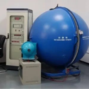
In waterproof testing lab, we often find that field-cut strips fail IP65 tests quickly. Cutting a finished product breaks its protective seal immediately, exposing the internal circuitry to moisture and dust.
Custom cutting compromises the original IP rating unless the supplier professionally reseals the cut end with silicone and a fitted end-cap. You must also account for the physical thickness of these end-caps and wire outlets, which typically add 3mm to 10mm to the overall installed length.
The "End-Cap Tax" on Length
One of the most common mistakes we see is ignoring the thickness of the accessories. If you have a 1000mm gap, and you order a 1000mm waterproof strip, it will not fit.
Why? Because the silicone end-cap adds physical length.
- Standard End-Cap: Adds ~3mm per end.
- Wire Outlet Cap: Can add ~5-8mm depending on the strain relief.
If you order a custom length, you must clarify if the length specified includes the end-caps or just the illuminated body. We recommend specifying "Total Overall Length (TOL) including end-caps."
Factory Resealing vs. Field Resealing
If you buy IP67 (silicone tube) or IP68 (fully encased) strips, the factory seals the ends using injection molding or high-grade glue that cures over 24 hours.
When you cut this strip on-site:
- Seal Integrity: You are relying on a manual application of glue. If there is an air bubble, water will get in via capillary action.
- Warranty: Most manufacturers (including us) void the waterproof warranty if the strip is cut by the user.
For high-stakes outdoor projects, it is safer to pay the supplier to produce the exact lengths at the factory. We can injection-mold the connectors onto the custom lengths, ensuring a bond that is far superior to anything you can achieve with a tube of glue on a dusty construction site.
The Impact of Wire Exit Direction
The fitment also depends on where the wire comes out.
- Straight Exit: Wire comes out the end. Adds the most length.
- Side/Bottom Exit: Wire comes out the side or back. Saves length but requires a wider or deeper profile.
IP Rating Risks with Custom Lengths
| IP Rating | Construction | Risk of Field Cutting | Recommendation |
|---|---|---|---|
| IP20 (Non-waterproof) | Bare PCB | None | Safe to cut and solder on site. |
| IP54 (Gel Coating) | Surface Glue | Low | Dab silicone on the cut end to prevent peeling. |
| IP67 (Silicone Tube) | Hollow Tube | High | Difficult to seal perfectly; recommend factory pre-cut. |
| IP68 (Solid Extrusion) | Solid Silicone | Critical | Do not cut on site. Factory custom order only. |
How do I ensure the cut points align perfectly with my aluminum profile dimensions?
We advise our partners to measure their aluminum channels before finalizing strip orders. A mismatch between the profile length and the strip's cutting unit creates shadows at the ends of the fixture.
Ensure alignment by calculating if your profile length is an exact multiple of the strip's cutting increment. Request the "First LED Offset" spec to center the light within the channel, and consider using 12V strips with shorter 25mm increments to minimize the unlit "dead space" at the ends.
The Math of Multiples
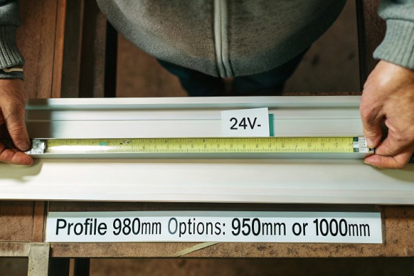
If you have a 24V COB strip with a 50mm cutting increment, your strip length can only be 50mm, 100mm, 150mm, etc.
If your cabinet width is 980mm, you have a problem.
- Option A: Cut at 950mm. Result: 30mm of dark space (15mm gap at each end).
- Option B: Cut at 1000mm. Result: Strip doesn't fit.
You cannot force the physics of the circuit. You must design the joinery around the light, or choose a light that fits the joinery.
Centering the Light (Symmetry)
To avoid a lopsided look where one end is bright and the other is dark, you need to center the strip.
- Dark Space Calculation: (Profile Length - Strip Length) / 2.
- In the 980mm example above, using a 950mm strip leaves 30mm total gap. You should center the strip so there is a 15mm gap on the left and 15mm on the right.
The "First LED Offset"
Another hidden variable is the distance from the cut mark to the first actual LED chip. On some strips, the first LED might be 5mm away from the cut line. On others, it might be right at the edge.
- Why it matters: If you are butt-jointing two profiles together to make a corner, a large offset will create a visible dark spot at the corner.
- Solution: Ask for the technical drawing showing the "First LED Pitch." For continuous lines of light, this pitch should be half the distance of the spacing between LEDs.
Practical Checklist for Profile Alignment
- Measure Twice: Don't use the architectural plans; measure the actual built cabinet. Joinery often deviates by millimeters.
- Select Voltage Wisely: If you have many short, irregular lengths, choose 12V (25mm cuts) over 24V. The smaller increment reduces the maximum possible dark gap from 49mm to 24mm.
- Mock-Up: Before ordering 500 meters, buy one reel and one profile. Cut it, install it, and power it up. Send a photo to the client to confirm the "dark edges" are acceptable.
- Cover the Gaps: If the dark edges are unavoidable, use profiles with opaque end-caps that cover the first 10-15mm of the diffuser. This hides the unlit wire connection area and makes the light appear to fill the whole visible bar.
Conclusion
Confirming tolerances is about turning assumptions into numbers. By defining negative tolerances (+0/-4mm), matching your profile lengths to the strip's cutting increments (25mm/50mm), and accounting for end-cap thickness, you eliminate the risks of rework. Clear communication with your supplier upfront prevents costly failures on site.