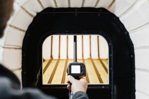
When we test new batches of high-density COB strips in aging room, the most common failure point isn't the diode itself—it's the gradual dimming at the tail end of a long run. There is nothing more frustrating for a contractor than installing twenty meters of seamless linear lighting, only to find the last five meters look yellowish or dim compared to the start. We have seen countless project delays caused by purchasing managers accepting a generic "10 meters" spec from a datasheet without understanding the electrical reality behind it. To avoid costly rewiring on site 1, you need to interrogate the physics behind the supplier's claims.
To determine the true maximum run length, you must provide your supplier with specific project parameters: input voltage (24V vs 48V), wattage per meter, and your tolerance for brightness decay. Do not accept a generic length; demand a calculation based on a maximum 10% voltage drop at the strip's end.
Let's break down the technical questions you need to ask to ensure your linear lighting remains consistent from start to finish.
What Is the Maximum Continuous Run Length for 24V COB Strips Before Voltage Drop Occurs?
In our daily interactions with electrical contractors, we notice a dangerous assumption that "24V" automatically implies long-run capability. While 24V is superior to 12V, the high power density of dotless COB strips creates significant resistance issues that many standard datasheets gloss over.
For high-density 24V COB strips, the safe maximum continuous run is typically between 5 to 10 meters depending on wattage. You must ask the supplier for the specific voltage drop curve at your required wattage per meter, as higher power consumption drastically shortens the viable run length.

Understanding the Physics of Voltage Drop in COB
When we engineer a high-density COB strip (often packing 480 to 500+ chips per meter), we are essentially creating a very long, thin resistor. The copper traces on the Flexible PCB (FPCB) have internal resistance 2. As current travels down the strip to power those hundreds of LEDs, voltage is lost as heat.
If you feed 24V at the start, you might only have 21V at the 10-meter mark. This phenomenon is called Voltage Drop.
In standard SMD strips (like the old 5050 models), the LEDs were spaced out, drawing less current per meter. However, the "dotless" appeal of COB strips comes from high density, which usually translates to higher wattage (often 10W/m to 15W/m). Higher wattage means more current flowing through the copper traces. According to Ohm's Law 3, higher current through a fixed resistance results in a larger voltage drop.
Critical Questions for Your Supplier
Don't just ask, "How long can it run?" That is too vague. You need to ask: "At what specific wattage does this run length apply?"
If a supplier tells you their 24V COB strip can run 15 meters from one end, be skeptical. They are likely either using a very low wattage (dim) strip or they are ignoring the visible brightness drop at the end.
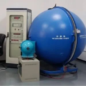
Here is a breakdown of typical limits we observe in our lab testing 4 for standard Constant Voltage (CV) 24V COB strips:
Typical Max Run Lengths for 24V Constant Voltage COB Strips
| Wattage Density | Power Draw (W/m) | Max Run (Single End Feed) | Risk at Max Length |
|---|---|---|---|
| Low Power | 5W - 8W | 8m - 10m | Minimal dimming, safe for most coves. |
| Medium Power | 10W - 12W | 5m - 7m | Visible dimming beyond 7m; heat buildup. |
| High Power | 14W - 20W | 3m - 5m | Significant voltage drop; requires frequent power injection. |
The "Safe" vs. "Possible" Distinction
When we define specs for our OEM clients, we distinguish between "electrical continuity" and "visual uniformity." A strip might technically light up at 15 meters, but if the end is 30% dimmer than the start, it is a failure for architectural applications.
Always ask your supplier to define their "Max Run" based on a 10% voltage drop threshold. Anything higher than 10% will result in visible dimming or, worse, a color shift where the white light starts looking pink or brown at the end of the run.
Should I Switch to 48V Constant Current Strips for Projects Requiring Longer Linear Lighting?
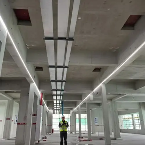
We often advise lighting designers who are working on large commercial spaces—like hotel corridors or airport terminals—to abandon 24V systems entirely. The logistical nightmare of hiding power supplies 5 every 5 meters is simply not worth it when superior technology exists.
Switching to 48V Constant Current (CC) strips is the most effective solution for runs exceeding 20 meters. The higher voltage reduces current draw, while the onboard IC chips regulate power to ensure the last LED is exactly as bright as the first, eliminating gradient dimming.
The High-Voltage Advantage
Why does 48V change the game? It comes down to current. To achieve the same wattage (brightness), a 48V system requires half the current (Amps) of a 24V system. Since voltage drop is driven by current, halving the amps significantly reduces the loss over distance.
However, voltage alone isn't the magic bullet. The real hero in long-run applications is Constant Current (CC) IC technology.
Constant Voltage (CV) vs. Constant Current (CC)
Most standard strips are Constant Voltage. They rely on resistors. If the voltage drops from 24V to 22V, the LEDs simply get dimmer.
Constant Current strips have tiny Integrated Circuits (ICs) built onto the PCB. These ICs act like gatekeepers. Even if the voltage drops from 48V down to 42V at the end of a 30-meter run, the IC ensures the LED still receives the exact current it needs to shine at full brightness.
When we co-develop products for large infrastructure projects, we almost exclusively specify 48V CC strips. It simplifies the wiring topology for the electrician, reducing labor costs significantly.
Technology Comparison for Long Runs
| Feature | 24V Constant Voltage (Standard) | 24V Constant Current (CC) | 48V Constant Current (CC) |
|---|---|---|---|
| Max Run Length | 5 - 10 meters | 15 - 20 meters | 30 - 50+ meters |
| Brightness Uniformity | Fades at the end | Perfect uniformity | Perfect uniformity |
| Cut Points | Every 2.5 - 5 cm | Every 10 - 15 cm | Every 10 - 20 cm |
| PCB Complexity | Simple (Resistors) | Moderate (ICs) | Complex (ICs + Thicker Copper) |
| Cost | Low | Medium | High |
When to Stick with 24V
Despite the benefits of 48V CC, we don't recommend it for every project. If you are lighting standard residential kitchen cabinets 6 or small joinery, 48V is overkill.
- Cutting Increments: 48V strips often have longer cutting increments (e.g., every 100mm or 166mm) compared to 24V (every 50mm). This makes them less precise for fitting into tight custom joinery.
- Power Supply Availability: 24V drivers are ubiquitous and cheap. 48V drivers are becoming common but are still pricier and larger.
- Safety Regulations: While 48V is generally considered low voltage, some jurisdictions have stricter rules for anything above 30V DC in wet areas. Always check local codes.
How Does Powering the Strip from Both Ends Affect the Maximum Usable Length?
In our experience troubleshooting on-site installations, we find that many "defective" strips are actually just victims of poor wiring layouts. Contractors often try to power a 15-meter run from one side and blame the product when it fails, rather than adjusting their feed strategy.
Powering a strip from both ends effectively doubles the maximum usable run length by reducing the distance current must travel to the center. This method, known as a dual-end feed, minimizes voltage drop and ensures consistent thermal performance across the entire installation.
The "Meeting in the Middle" Principle
When you power a strip from only one end, the electrons have to push through the entire length of the copper trace to reach the last LED. By the time they get there, they are "tired" (voltage has dropped).
When you connect the positive and negative wires to both the start and the end of the strip (and connect them to the same power supply), the current flows from both sides and meets in the middle. Effectively, a 10-meter strip powered from both ends behaves electrically like two 5-meter strips placed back-to-back.
This is a crucial question to ask your supplier: "Is your stated max run length based on a single-end feed or a dual-end feed?" Many suppliers will list the dual-end spec on their datasheet because it looks more impressive, without explicitly stating that you need to wire it that way.
The Role of PCB Copper Thickness
This is a hidden spec that separates professional-grade strips from budget ones. The thickness of the copper on the PCB 7 is measured in ounces (oz).
- 1oz Copper: Standard for cheap strips. High resistance, short runs.
- 2oz Copper: The minimum standard we use for project-grade strips.
- 3oz - 4oz Copper: Required for high-power, long-run high-density COB strips.
Thicker copper acts like a wider highway for the electrons, reducing traffic jams (resistance) and heat. Always ask your supplier: "What is the copper thickness of the PCB? Is it 2oz or 3oz?" If they don't know, or if they say 1oz for a high-wattage strip, walk away.
Wiring Configuration Impact on Run Length (Example: 10W/m 24V COB)
| Wiring Method | Effective Max Length | Pros | Cons |
|---|---|---|---|
| Single End Feed | ~7 meters | Easiest installation; only one wire drop needed. | Shortest run; highest voltage drop at end. |
| Dual End Feed | ~14 meters | Doubles length; uniform brightness. | Requires running a return wire to the end of the run. |
| Center Feed | ~14 meters | Similar to dual feed; good for custom cuts. | Wire joint in the middle of the strip can be unsightly. |
Installation Realities
While dual-end feeding solves the physics problem, it creates an installation challenge. You need to run a wire from the power supply all the way to the far end of the strip. In a finished ceiling or a routed channel in a cabinet, there might not be space for this extra wire.
This is why we emphasize calculating the Single End max run first. If your project requires 8 meters and the single-end limit is 7 meters, you must plan for a dual feed or accept the dimming. Don't hope for the best.
Will I See Visible Brightness Attenuation at the End of a 10-Meter Run?
We have received return shipments where the customer claimed the LEDs were "defective" because the color temperature looked "muddy" at the end of the run. In reality, the LEDs were fine; the voltage drop had caused a spectral shift that the human eye is incredibly sensitive to detecting.
Visible brightness attenuation typically becomes noticeable when voltage drops by more than 10-15%, often manifesting as a color shift toward red before perceived dimming occurs. You must ask suppliers for the chromaticity shift threshold, not just the lumen maintenance data.
The "Pink Shift" Phenomenon
With white COB LEDs, the light is actually generated by a blue LED chip covered in yellow phosphor. The blue light passes through the phosphor to create white.
Here is the critical insight: The blue LED chip 8 requires a specific forward voltage to operate efficiently. When voltage drops significantly due to a long run, the blue chip's output weakens faster than the phosphor's response. The result? The light starts to look warmer, pinkish, or brownish.
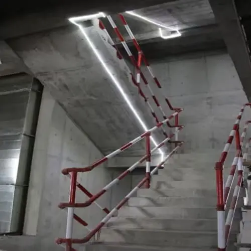
This Chromaticity Shift often happens before you notice the strip getting dimmer. Your eyes adjust to brightness changes (auto-exposure), but they are very sensitive to color differences. If you have two strips meeting in a corner—one powered fresh from the source and one at the tail end of a 10m run—the color mismatch will be obvious and unacceptable for high-end interiors.
Thermal Derating and Enclosed Channels
Another factor that suppliers rarely mention is heat. Resistance increases with temperature.
- Cold Start: When you first turn on the strip, it might look fine.
- Heat Soak: After 30 minutes, the strip heats up. The copper resistance increases.
- Voltage Drop Worsens: The increased resistance causes more voltage drop.
- Runaway Effect: The end of the strip gets even dimmer.
If you are installing high-density COB strips inside an aluminum profile with a plastic diffuser (which traps heat), the "Max Run Length" listed on the datasheet might decrease by 10-20%.
Critical Checklist for Your Supplier
To get the real data, copy and paste these questions to your potential supplier:
Supplier Interrogation Checklist
| Question Category | Specific Question to Ask | Desired Answer |
|---|---|---|
| Definition of Max | "Is the max run length calculated based on visible dimming or electrical safety?" | Should be based on <10% voltage drop or visible uniformity. |
| Color Consistency | "Does the strip exhibit chromaticity shift (pink/yellow) at the max run length?" | Honest suppliers will provide a "Yes" if pushed beyond limits, or data on SDCM stability. |
| Thermal Impact | "How does the max run length change if installed in an enclosed IP65 tube or channel?" | Should acknowledge a reduction in length due to heat/resistance. |
| Connection Rating | "What is the max current rating of the solder pads or connectors?" | Critical safety question. Even if the strip can handle the run, the connector might melt if it exceeds 4-5 Amps. |
Conclusion
There is no magic "one-size-fits-all" answer to how long a COB strip can run. It is a calculation involving voltage, copper thickness, wattage, and your tolerance for imperfection.
voltage is lost as heat 9
When you source these products, stop asking "How long is the roll?" and start asking, "What is the voltage drop curve at 10 meters?" By forcing the supplier to do the math based on your specific project constraints—whether it's a 24V residential cove or a 48V commercial corridor—you protect yourself from the embarrassment of uneven lighting and the cost of tearing out drywall to fix it.
color mismatch 10
Footnotes
- Safety standards for electrical wiring and installations on construction sites. ↩︎
- Explains the physics of internal resistance in conductors like PCB traces. ↩︎
- Reference for fundamental electrical principles used in calculating voltage drop. ↩︎
- Standard for quality management systems in testing and calibration environments. ↩︎
- Leading manufacturer of LED drivers showing availability and specs for power systems. ↩︎
- Official guidance on LED lighting efficiency and residential applications. ↩︎
- Technical explanation of copper weight and thickness in PCB manufacturing. ↩︎
- Background information on LED technology and phosphor conversion. ↩︎
- General reference for the electrical engineering concept of voltage drop. ↩︎
- Authoritative source for lighting standards and color consistency metrics. ↩︎