We often see contractors struggle with LED strips that snap or fail during complex installations, usually because the product looked robust on a datasheet but lacked structural integrity in reality. In testing lab, we know that "durability" isn't just a marketing buzzword; it is a measurable physics problem involving copper thickness, solder joints, and manufacturing continuity. When you are sourcing for a high-stakes commercial project, simply asking "is this strong?" will only get you a polite "yes." You need to dig deeper into the engineering limits of the flexible PCB (FPCB) to ensure the lights stay on long after the crew leaves the site.
To accurately assess tensile strength, do not ask generic questions about durability. Instead, specifically request data on the solder pad pull force limit (measured in Newtons), confirm if the PCB uses a continuous reel-to-reel manufacturing process to eliminate weak splice points, and verify the copper weight is at least 2oz to 3oz for structural reinforcement.
Let’s break down the specific technical inquiries you need to make to filter out low-quality suppliers and secure project-grade COB strips.
What Specific Technical Datasheets Should I Request to Verify the Tensile Strength of COB Strips?
When we prepare documentation for our European and Australian partners, we know that a standard lumen report is not enough to prove mechanical reliability. We frequently encounter buyers who focus solely on optical parameters, overlooking the mechanical data that predicts whether a strip will survive being pulled through a tight aluminum channel. A lack of specific mechanical data is often a red flag that the manufacturer has not stress-tested their product for real-world construction environments.
You must request a mechanical stress test report referencing IEC 60598-1 Section 4 or an equivalent standard that details the specific pulling force limit. Additionally, explicitly ask for a "Reel-to-Reel" manufacturing certificate to confirm the strip is not composed of multiple 0.5-meter sections hand-soldered together, as these manual joints are the first to fail under tension.
The Critical Difference: Reel-to-Reel vs. Soldered Sections
The most revealing document you can request regarding tensile strength isn't actually a "strength" test—it is the manufacturing process specification. In the LED industry, there are two ways to make a 5-meter roll of COB strip.
- The Cheap Way (Soldered Sections): The factory produces 0.5-meter rigid sections and hand-solders them together to form a reel.
- The Professional Way (Reel-to-Reel): The FPCB is manufactured as one continuous, seamless copper circuit board without intermediate joints.
If you look closely at a budget strip, you might see a solder joint every 50cm. In our experience, these joints reduce the tensile strength of the strip by over 60%. When a contractor pulls the strip during installation, the tension concentrates on these stiff solder points, causing them to crack. A continuous reel-to-reel strip distributes tension evenly across the entire length of the copper.
Requesting the "Open Circuit" Failure Report
Another specific document to ask for is the "Failure Mode Analysis" or FMA report. You want to know what happens when the tensile limit is exceeded. Does the PCB snap? Or do the internal flip-chip connections break first?
For high-density COB strips (often 480 chips/m or higher), the phosphor gel is continuous. If the PCB stretches even slightly beyond its elastic limit, the brittle phosphor layer can crack, or the microscopic connections between the flip-chip and the board can sever. This results in "dead sections."
Checklist for Supplier Documentation
Use the following table to audit the documents your potential supplier provides. If they cannot provide the "Project-Grade" items, proceed with caution.
Supplier Documentation Audit Checklist
| Document Type | Standard / Budget Supplier Response | Project-Grade Supplier Response | Why It Matters |
|---|---|---|---|
| Manufacturing Process | "Standard Production" (Vague) | Reel-to-Reel (Continuous FPCB) | Eliminates weak solder joints every 0.5m that break under tension. |
| Mechanical Standard | None or General CE | IEC 60598-1 (Section 4) | Proves the product was tested against specific mechanical force standards. |
| Adhesive Spec | "Strong Tape" | 3M VHB or 300LSE Datasheet | High-strength adhesive reduces reliance on the PCB's own tensile strength by bonding firmly to the channel. |
| Warranty Terms | Covers "Light Failure" | Covers "Open Circuit" & "Joint Failure" | Specifically protects you against breakage caused by installation stress (within limits). |
By demanding these specific documents, you signal to the supplier that you understand the manufacturing process. This usually stops them from offering you their lower-tier "economy" products.
How Do I Determine If the PCB Thickness Is Sufficient to Withstand Installation Tension?
In engineering meetings, we often debate the balance between flexibility and rigidity. A PCB that is too thin feels flimsy and stretches like a rubber band, destroying the circuitry, while one that is too thick becomes brittle and hard to install in corners. We have found that for B2B projects, especially those involving long runs, the physical dimensions of the Printed Circuit Board are a primary indicator of its ability to handle the push and pull of installation.
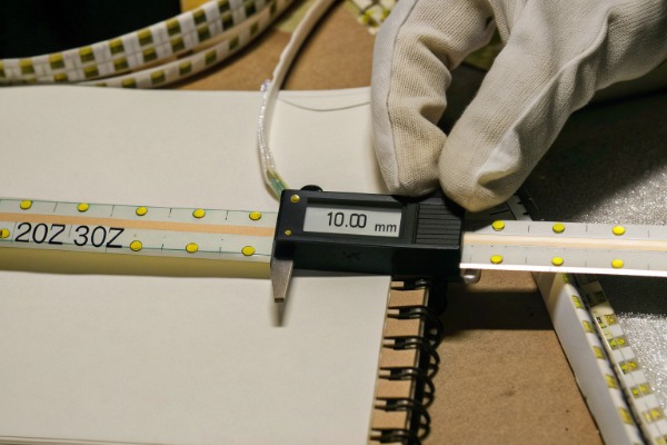
To ensure sufficient structural integrity, verify that the PCB width is at least 10mm for high-wattage or high-density models and that the copper weight is a minimum of 2oz (preferably 3oz). A wider and thicker board distributes mechanical stress more effectively, preventing the microscopic circuitry from tearing during handling.
The Role of Copper Weight in Tensile Strength
When we talk about "PCB Thickness," we are mostly talking about the copper. The plastic substrate (polyimide) is relatively standard, but the copper layer is the backbone.
In the market, you will find three common tiers:
- 1oz Copper: Common in cheap, low-power strips. It tears easily like paper.
- 2oz Copper: The industry standard for professional strips. It offers a good balance of flexibility and strength.
- 3oz or 4oz Copper: Used for high-power or ultra-long-run strips. It is very difficult to snap but harder to bend around tight corners.
For high-density COB strips, which generate significant heat, the copper serves a dual purpose: Heat Dissipation and Tensile Reinforcement. If a supplier tries to sell you a high-density strip (e.g., 15W/m) with 1oz copper, it will likely fail. The heat will soften the adhesive and the substrate, and the weak copper will snap under the slightest tension.
PCB Width: 8mm vs. 10mm vs. 12mm
Standard LED strips are often 8mm wide. However, for high-density COB, we strongly recommend specifying a 10mm or 12mm width.
Why? It is simple physics. A wider strip has more surface area to grip the adhesive and more substrate material to absorb pulling forces. An 8mm strip is much more prone to twisting. Twisting is the enemy of tensile strength. When a strip twists inside a profile, the torque force shears the internal connections. A 10mm or 12mm strip naturally resists twisting, keeping the tension linear where the copper is strongest.
Analyzing the Layer Structure
You should also ask about the Coverlay (cover layer). A high-quality FPCB for COB strips should be "Double-Sided." This means there is copper on both the top and bottom, connected by vias (small holes). This sandwich structure is infinitely stronger than a single-sided PCB.
Recommended PCB Specs Based on Application
| Application Scenario | Recommended PCB Width | Minimum Copper Weight | Tensile Risk Level |
|---|---|---|---|
| Cabinet / Shelf Lighting | 8mm | 2oz | Low (Short runs, low tension) |
| Cove Lighting (Long Run) | 10mm | 3oz | High (Long pulls, weight of strip) |
| Suspended / Linear Profiles | 10mm or 12mm | 3oz | Medium (Installation friction) |
| Outdoor / IP67 Extrusion | 10mm or 12mm | 3oz + Silicone Fill | Very High (Thermal expansion stress) |
If a supplier cannot confirm the copper weight or tries to tell you that "1oz is enough for COB," they are prioritizing cost over your project's safety.
What Is the Maximum Pulling Force I Should Specify for High-Density Dotless LED Strips?
When we calibrate the automated soldering machines on our production line, we are acutely aware that the weakest point of any LED strip is not the middle of the board—it is the connection point. We have seen countless instances where a contractor claims the "strip broke," but in reality, the lead wire ripped the solder pad right off the PCB. Understanding the specific force limits helps you set realistic expectations for your installation teams and hold suppliers accountable for weak manufacturing.
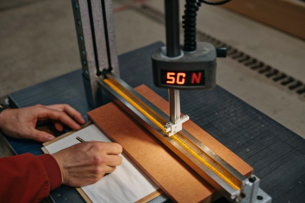
You should specify a minimum pull force of 50 Newtons (approx. 5kg) for the PCB body itself, but more importantly, require a "Strain Relief" reinforcement on the lead wires that can withstand at least 30 Newtons. Without secondary glue or resin reinforcement at the solder joints, the wire connection will almost always fail before the strip itself reaches its tensile limit.
The "Weakest Link" Reality: Solder Pads
It is rare for a technician to pull a strip so hard that the copper tape snaps in half. That requires significant force. The most common failure mode during installation is Pad Detachment.
This happens when the lead wires (the power cables) are pulled. The solder pad is only a thin layer of copper glued to the plastic substrate. If you pull the wire, you are applying peeling force to that tiny area.
How to Ask the Supplier:
- "Do you apply secondary resin or silicone glue over the solder joints?"
- "What is the peel strength of your solder pads?"
A professional supplier will apply a blob of clear or white silicone glue over the solder point. This acts as Strain Relief, transferring the force from the delicate solder joint to the wider PCB body.
Quantifying the Force: Newtons vs. Kilograms
While "kg" is easier to visualize, engineering specs usually use Newtons (N).
- 10N (~1kg): Very weak. Avoid.
- 30N (~3kg): Acceptable for standard handling.
- 50N+ (~5kg+): Project grade.
For high-density COB strips, the internal structure is more delicate because there are hundreds of tiny chips. Excessive stretching (even if it doesn't snap the board) can cause Micro-Cracking. This is where the board stretches, but the brittle LED chip or the phosphor coating does not. The result is a strip that lights up but has dark spots or flickers when touched.
Installation Protocols to Protect Tensile Strength
Even the strongest strip has limits. You should ask the supplier for their Maximum Run Length relative to tensile load. For example, if you are hanging a strip vertically (like in an elevator shaft or a tall atrium), gravity exerts a constant tensile force.
Pull Force Thresholds and Failure Modes
| Component Tested | Minimum Acceptable Force | Ideal Project Spec | Common Failure Mode |
|---|---|---|---|
| Lead Wire Connection | > 20 N | > 40 N (with Glue) | Pad lifts off PCB; Wire snaps off solder. |
| PCB Body (Longitudinal) | > 40 N | > 60 N | Copper traces crack; Phosphor layer splits. |
| Peel Strength (Adhesive) | > 10 N / 25mm | > 15 N / 25mm | Strip detaches from surface, sagging creates tension. |
| Connector (Solderless) | > 15 N | Avoid if possible | Connector slides off; Poor contact. |
Critical Insight: Always prefer soldered connections with strain relief over "solderless connectors" (hippos/clips) for high-tension areas. Solderless connectors have very low pull resistance and often cut into the PCB, weakening it further.
Does the Copper Weight in the FPCB Affect the Overall Durability and Tensile Strength?
We view copper as the skeleton of the LED strip; without a strong skeleton, the body collapses. When sourcing raw materials, we pay a premium for high-quality rolled annealed copper because we know that the relationship between copper weight and durability is linear. Many buyers mistakenly believe copper weight is only about electrical conductivity and voltage drop, failing to realize it is the primary factor preventing mechanical elongation and breakage.
Yes, the copper weight is the single most critical factor influencing the tensile strength and durability of the FPCB. Thicker copper (3oz or 4oz) significantly reduces the risk of the strip stretching during installation, which prevents the microscopic internal circuits and flip-chip bonds from severing under mechanical stress.
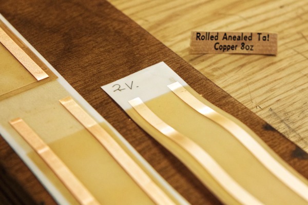
Rolled Annealed Copper vs. Electrolytic Copper
It is not just about the weight (2oz vs 3oz); it is also about the type of copper.
- Electrolytic Copper: Cheaper. It is formed by plating. It is more brittle.
- Rolled Annealed (RA) Copper: More expensive. It is formed by rolling. It is much more flexible and resistant to fatigue.
For COB strips, which are often bent into organic shapes, RA Copper is essential. It allows the strip to bend without the copper grains cracking. When you ask about copper weight, also ask: "Is this Rolled Annealed copper or Electrolytic?"
Thermal Expansion and Mechanical Stress
Copper weight plays a hidden role in durability regarding Thermal Expansion. LED strips heat up and cool down every day. This cycle causes materials to expand and contract.
If the copper is too thin (1oz), it heats up rapidly and expands at a different rate than the polyimide substrate and the silicone phosphor. This mismatch creates internal mechanical stress—literally pulling the strip apart from the inside out over time. Thicker copper (3oz) acts as a better heat sink, keeping the temperature lower and more stable, thus reducing this thermal mechanical stress.
The "Double-Sided" Advantage
We briefly mentioned this earlier, but it deserves a deeper look regarding durability. A Double-Sided FPCB has copper layers on both sides. This creates a "I-beam" effect, structurally reinforcing the strip.
Single-sided PCBs are prone to curling and warping. When a contractor tries to flatten a warped strip onto a surface, they apply tension. A double-sided, heavy-copper PCB lays flat naturally, reducing the need for force during installation.
Summary of Copper Benefits
- Tensile Strength: Resists stretching during wire pulling.
- Shear Strength: Resists tearing at the solder pads.
- Thermal Durability: Reduces expansion/contraction stress.
- Voltage Stability: Ensures the LEDs at the end are as bright as the start (reducing the need to over-drive the current).
Pro Tip: If you are buying "Long Run" COB strips (e.g., 10 meters or 15 meters powered from one end), the copper weight must be 3oz or 4oz. The physics of voltage drop demands it, and the added weight of the long reel demands the extra structural strength.
Conclusion
Asking about tensile strength requires moving beyond simple questions of "is it strong?" to specific inquiries about manufacturing and materials. By requesting data on Reel-to-Reel production, solder pad pull force (Newtons), and Copper Weight (2oz+), you filter out suppliers who cut corners. Remember, for high-density COB strips, the goal isn't just to prevent the strip from snapping in half, but to prevent the microscopic stretching that kills the delicate flip-chip connections.