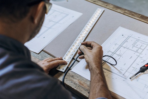
When we analyze returned products in our lab, the culprit is rarely the LED chip itself but often an inadequate circuit board design that traps heat.
The PCB width, copper thickness, and layer structure are the critical factors determining heat dissipation and voltage stability. A minimum 10mm width and 2oz copper weight are essential for high-density COB strips to prevent overheating, voltage drop, and premature light decay.
Let's examine the specific technical parameters you must verify to ensure your lighting projects 1 stand the test of time.
Does PCB Copper Thickness Really Affect the Voltage Drop and Lifespan of My COB Strips?
During our internal aging tests, we frequently see thin copper traces causing significant dimming at the end of long runs, ruining the visual consistency contractors demand.
Yes, copper thickness is the decisive factor for electrical efficiency and thermal management. Using 2oz or 3oz copper reduces internal resistance, minimizing voltage drop over long distances while acting as a primary heat sink to extend the operational lifespan of the LEDs.
The Physics of Voltage Drop and Resistance
In the world of high-density COB lighting, the Printed Circuit Board (PCB) is not just a holder for chips; it is the main highway for electricity. Standard LED strips often use 1oz (35µm) copper. While this is sufficient for low-power SMD strips, it creates a bottleneck for the high current required by high-density COB arrays (often exceeding 15W/m).
When the copper is too thin, resistance increases. This resistance converts valuable electrical energy into waste heat rather than light. This leads to two major problems for your projects:
- Visible Voltage Drop: The LEDs at the end of a 5-meter reel look noticeably dimmer than those at the start.
- Thermal Stress: The excess heat generated by resistance stays trapped in the copper traces, raising the operating temperature of the LED chips and shortening their life.
Rolled Annealed Copper vs. Electrolytic Copper
Beyond just thickness, the type of copper matters. In our manufacturing process, we prioritize Rolled Annealed Copper over standard Electrolytic Copper. Rolled copper has an elongated grain structure. This makes the PCB far more resistant to fatigue. When installers bend the strip around corners or into profiles, rolled copper flexes without cracking. Electrolytic copper is brittle and prone to micro-fractures during installation, which can cause dead sections months after the project is finished.
Choosing the Right Thickness for Your Project
To help you decide, we have compiled a comparison of common copper weights and their suitability for different project types.
| Copper Weight | Thickness (approx.) | Best Application | Max Recommended Power |
|---|---|---|---|
| 1oz (Standard) | 35µm | Decorative, low-brightness accent lighting. | Up to 9.6 W/m |
| 2oz (Professional) | 70µm | Main lighting, commercial linear lights, long runs. | Up to 18 W/m |
| 3oz (Industrial) | 105µm | High-power architectural lighting, outdoor IP67/68. | Above 18 W/m |
| 4oz (Specialty) | 140µm | Ultra-long runs (e.g., 10m-20m single feed). | High Current Loads |
For any project-grade COB strip, we strongly advise against anything less than 2oz. It provides the necessary thermal mass to pull heat away from the dense array of chips, ensuring the color temperature remains stable over years of use.
What Is the Optimal PCB Width to Ensure Proper Heat Dissipation for High-Density LEDs?
Our engineers often reject custom requests for high-wattage chips on narrow boards because the physics of heat transfer 2 simply does not work without sufficient surface area.
The optimal PCB width for high-density COB strips is 10mm or 12mm. While 8mm or 5mm strips exist for compact spaces, they lack the surface area required to dissipate heat effectively, leading to rapid temperature spikes and reduced reliability in high-power applications.
Surface Area: The Key to Thermal Management
There is a current trend in the market towards "invisible" lighting, pushing for ultra-slim 5mm or even 3mm PCBs. While these fit into tiny grooves in cabinetry, they pose a significant risk if not managed correctly. Heat dissipation is directly proportional to surface area.
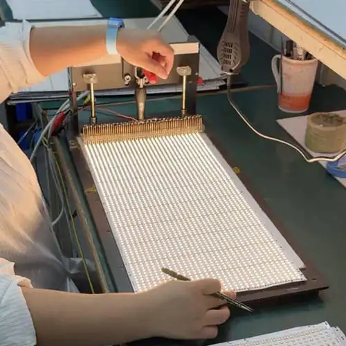
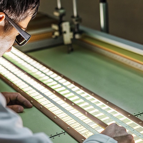
A high-density COB strip packs hundreds of chips per meter (e.g., 480 or 512 LEDs/m). These chips generate heat in a very concentrated line. A wider PCB acts as a larger radiator.
- 8mm PCB: The industry standard for years. It is acceptable for standard wattage (up to 10W/m). However, for dotless COB strips running at higher brightness, 8mm often runs hot.
- 10mm PCB: This is the "sweet spot" for professional lighting. The extra 2mm adds 25% more surface area compared to 8mm. This significantly lowers the junction temperature of the LEDs.
- 12mm+ PCB: For high-output architectural lighting (20W/m+), a 12mm board is mandatory to ensure the warranty period can be met without failure.
Impact on Installation and Profiles
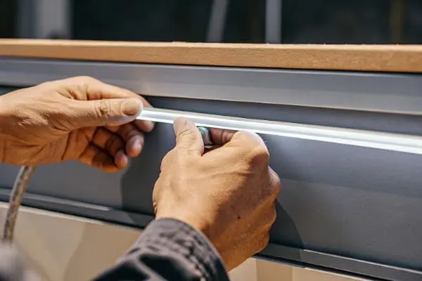
When we design our product lines, we match the PCB width to standard aluminum profiles. However, using a wider PCB also improves the mechanical stability of the installation. Narrow 5mm strips are difficult to adhere perfectly straight; they tend to twist or peel off the aluminum channel. A 10mm or 12mm strip sits flat, ensuring the 3M adhesive tape 3 makes full contact with the heat sink (the aluminum profile). This contact is crucial because air gaps act as insulators, trapping heat.
Width vs. Power Recommendations
Below is a guide we use internally to determine safe operating limits based on PCB width.
| PCB Width | Recommended Max Power | Thermal Risk Level | Ideal Use Case |
|---|---|---|---|
| 5mm | < 8 W/m | High | Ultra-slim joinery, short runs only. |
| 8mm | < 12 W/m | Moderate | Standard cove lighting, residential. |
| 10mm | < 18 W/m | Low | Commercial offices, retail displays. |
| 12mm | < 24 W/m | Very Low | High-ceiling general lighting, exterior. |
The Trade-off of "Slim" Designs
We understand that designers love the look of a thin line of light. However, if you choose a 5mm COB strip, you must ensure it is mounted on a substantial aluminum bar. Never install narrow, high-density strips directly onto wood or drywall. The PCB alone cannot handle the thermal load. By upgrading to a 10mm PCB, you gain a safety margin that protects your reputation against early failures.
How Can I Verify If the Supplier Uses Double-Layer PCBs for Better Durability?
We strictly utilize double-layer boards in our production because single-layer alternatives are prone to microscopic cracks that cause intermittent flickering after installation.
You can verify a double-layer PCB by checking the cross-section for two distinct copper layers separated by a fiberglass core, or by requesting the UL file. Double-layer designs provide superior structural integrity and current capacity compared to fragile single-layer counterparts.
Why Structure Matters More Than Specs
Many suppliers will claim "2oz copper," but they might be applying it to a single-sided PCB to save cost. A Double-Layer PCB (2-sided) is the industry standard for professional-grade LED strips. It consists of:
- Top Copper Layer: Connects the LED chips and resistors.
- Dielectric Core (FR4): Insulates and provides mechanical strength.
- Bottom Copper Layer: Acts as a return path for current and a massive heat spreader.
In contrast, a single-layer PCB has copper only on one side. These are flimsy. When you bend them during installation, the copper traces are under extreme tension and can easily snap. A double-layer structure reinforces the strip, much like a beam in a building.
chemical finish 5
The "Peel Test" and Visual Inspection
If you have a sample in hand, you can perform a simple check.
- Visual Check: Look at the back of the strip (after peeling back a small section of 3M tape). On a double-layer board, the back surface is smooth and uniform, often showing the outline of the copper pour.
- The Peel Test: If you peel the copper foil off a cheap single-layer board, it comes off easily, often taking the solder mask with it. A high-quality double-layer board is bonded tightly to the fiberglass core.
The Hidden Hero: Dielectric Thermal Conductivity
Another factor we monitor closely is the Dielectric Layer. This is the insulation between the copper and the base. Even if you have thick copper, if the dielectric layer is a poor heat conductor, heat stays trapped near the LEDs.
- Standard FR4: Good for general use.
- High-Thermal FR4: Used in our high-power series. It transfers heat efficiently from the top layer (LEDs) to the bottom layer (aluminum profile).
Durability Comparison
| Feature | Single-Layer PCB | Double-Layer PCB |
|---|---|---|
| Bending Durability | Low (Prone to cracking) | High (Reinforced structure) |
| Heat Dissipation | Poor (Top side only) | Excellent (Top & Bottom dissipation) |
| Current Capacity | Limited | Doubled (Two paths for current) |
| Solder Pad Strength | Weak (Pads lift easily) | Strong (Through-hole connectivity) |
For contractors, the nightmare scenario is a strip that works during testing but fails after being glued into a ceiling cove. The mechanical strength of a double-layer PCB is your best insurance against this.
color temperature 6
Should I Specify a White or Yellow PCB Background for Better Light Reflection?
Our clients are often surprised when we advise against yellow or black PCBs for general lighting, as the board color significantly alters the total lumen output.
Dielectric Layer 7
You should always specify a high-quality white PCB for general lighting applications. A white solder mask reflects light outward, increasing overall system efficiency and ensuring color consistency, whereas yellow or dark PCBs absorb light and can cause color shifting.
The Optical Impact of Solder Mask
The color of the PCB comes from the Solder Mask, the protective coating applied over the copper. While it might seem like a purely aesthetic choice, it plays a functional role in COB strips.
- White PCB: Reflects approximately 90% of the light that hits it. Since COB LEDs have a wide beam angle (180°), a significant amount of light spills sideways onto the board. A white background bounces this light back out, maximizing brightness.
- Yellow/Brown PCB: often indicates a raw or cheaper finish (like OSP without a mask). It absorbs light, reducing the effective lumens per watt.
- Black PCB: Popular for cinemas or stage lighting where you want the strip to "disappear" when off. However, be aware that a black PCB can reduce light output by 15-20% due to absorption.
Surface Finish: ENIG vs. OSP
Beyond color, the chemical finish on the solder pads is critical.
- OSP (Organic Solderability Preservative): A thin organic coating. It is cheap but prone to oxidation. If the strip is stored for months before use, the pads can oxidize, leading to "cold solder joints" where the wire connection fails.
- ENIG (Electroless Nickel Immersion Gold): This is what we use for premium lines. It uses a layer of gold over nickel. It is perfectly flat (great for tiny COB chips) and never corrodes. If you are importing strips that might sit in a warehouse, ENIG is worth the extra cost.
Anti-Yellowing Resistance
One specific issue with COB strips is heat accumulation discoloring the white paint. If a supplier uses cheap ink, the white PCB will turn yellow or brown after 1,000 hours of use. This "yellowing" shifts the color of the light, making a 4000K strip look like 3500K or 3000K over time.
We insist on High-Temperature Resistant Ink. This ensures the white background stays white, maintaining the original color temperature of the light installation.
PCB Finish Selection Guide
| Parameter | Best Choice | Why? |
|---|---|---|
| Solder Mask Color | White | Max reflection, highest lumen efficiency. |
| Pad Finish | ENIG (Gold) | Oxidation resistance, reliable soldering. |
| Ink Type | Anti-Yellowing | Prevents color shift over time due to heat. |
When you specify your order, do not just ask for "COB Strip." Specify "White PCB with Anti-Yellowing Mask and ENIG Finish." This level of detail signals to suppliers that you know the difference between budget tape and professional lighting equipment.
Printed Circuit Board 9
Conclusion
To ensure reliable, long-lasting LED installations, prioritize a PCB width of at least 10mm, 2oz double-layer copper, and a high-quality white finish to maximize heat dissipation and light efficiency.
electrical energy 10
Footnotes
- Federal guidelines for architectural lighting systems and project standards. ↩︎
- Academic resource explaining the fundamental principles of thermal conduction. ↩︎
- Technical specifications for thermal conductive adhesive tapes used in LED strips. ↩︎
- General background on the SI unit for luminous flux. ↩︎
- Technical documentation on chemical surface finishes for high-reliability PCBs. ↩︎
- International standards body for light and color measurement. ↩︎
- International standard for environmental testing of electrical and electronic equipment. ↩︎
- Explains the metallurgical process of annealing for improved flexibility. ↩︎
- Global standards body for PCB design and manufacturing quality. ↩︎
- Official guidance on LED energy efficiency and thermal management. ↩︎