We often see samples that look perfect in a catalog but fail miserably once they reach the job site. We have found that not every COB strip is worthy of entering the project phase. Many quality risks are visible to the naked eye before you even apply power or use advanced testing instruments. If these workmanship defects are ignored during the sampling phase, they almost always amplify into costly rework, client complaints, or batch replacements later.
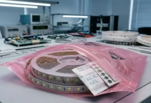
quality risks 1
To judge COB LED strip quality visually, inspect the PCB for a double-layer structure, ensure solder joints are smooth and shiny, and verify the silicone encapsulation is uniform without bubbles. High-quality strips feature clean cut points and genuine adhesive backing that does not peel easily.
Let's break down the specific visual cues you can use to filter out low-quality products immediately.
What signs of poor soldering and PCB construction should I look for on the backside?
When we audit our production lines, the backside of the strip often tells us more about durability than the front. Many suppliers hide poor engineering under the silicone coating, but the raw PCB and solder joints reveal the truth about the factory's process control.
Poor soldering manifests as dull, grainy "cold solder" joints or cracks, indicating weak electrical connections. On the PCB, look for single-layer boards where copper traces are clearly visible; premium strips use double-layer PCBs that appear shadowed, offering superior heat dissipation and durability.

The "Shadow" Test for PCB Layers
The printed circuit board (PCB) is the backbone of your LED strip. In our engineering experience, a single-layer PCB is a major red flag for COB products because high-density chips generate concentrated heat. If the heat cannot dissipate, the strip fails early.
You can identify the PCB quality by looking at the copper traces on the back (after peeling back a small section of tape if necessary):
- Single-Layer PCB: The electrical traces are clearly visible and distinct. This indicates a cheaper manufacturing process with less copper, leading to voltage drop and overheating.
- Double-Layer PCB: The traces appear "shadowed" or slightly obscured because there are overlapping layers of copper foil. This structure provides better current handling and heat management.
Solder Joint Integrity
Inspect the solder joints where the chips or resistors connect to the board. You do not need a microscope; a simple magnifying glass or your phone camera zoom works well.
- Shiny and Smooth: A high-quality joint is shiny, smooth, and has a concave "fillet" shape. This means the solder flowed correctly at the right temperature.
- Dull or Grainy: If the joint looks matte, grey, or grainy, it is a "cold solder" joint. This happens when the soldering iron was not hot enough or the strip was moved before cooling. These joints will crack when the strip is bent during installation.
- Flux Residue: Look for yellow or brown sticky spots around the pads. This residue is acidic and can corrode the copper over time, causing failure months after installation.
PCB White Oil and Copper Edges
Examine the white protective mask (oil) on the PCB. It should be applied evenly without bubbles. The edges of the copper pads should be clean. If you see "oil overflow" (white paint covering the metal pad) or irregular exposed copper, it indicates the PCB manufacturer uses low-precision equipment.
Visual Checklist for PCB and Soldering
| Inspection Point | High-Quality Indicator | Red Flag (Reject Sample) |
|---|---|---|
| Solder Finish | Shiny, smooth, concave shape | Dull, grainy, grey, or balled up |
| PCB Structure | Shadowed traces (Double-layer) | Clearly visible traces (Single-layer) |
| Cleanliness | Clean pads, no residue | Yellow flux residue, tin slag, dust |
| Mask Alignment | Precise openings around pads | White oil covering solder pads |
How can I tell if the phosphor coating on the COB strip is uniform enough to prevent color spotting?
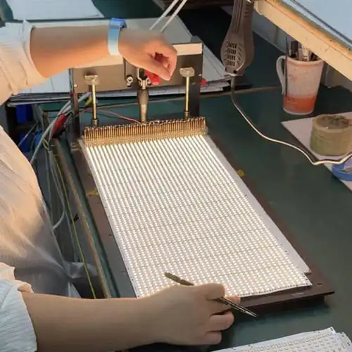
The "face" of a COB strip—the silicone and phosphor coating—determines the quality of light. In our daily quality control checks, we scan the strip from end to end. If the dispensing process is unstable, the light output will be inconsistent, regardless of the chip quality.
integrating sphere 3
Uniformity is critical; the phosphor coating must be continuous, smooth, and free of an "orange peel" texture or oily residue. Inconsistent width along the strip signals poor automation control, which inevitably leads to color temperature mismatches and uneven light distribution in the final installation.

Surface Texture and Cleanliness
Run your finger gently over the surface (we call this the "One Touch" inspection).
- High-Quality Gel: The surface should feel fine, smooth, and have a soft, matte reflection. It should not feel greasy or sticky.
- Low-Quality Gel: If the surface feels dry, rough, or oily, or looks like an "orange peel," it indicates low-grade silicone or poor mixing. These materials are prone to yellowing and cracking (gel splitting) after a few months of use.
Width Stability: The "Fluctuating Width" Issue
This is a subtle defect that many buyers miss. Look closely at the yellow phosphor strip. Does the width of the yellow line stay perfectly constant, or does it fluctuate (get wider and narrower) as you move down the strip?
- Consistent Width: Indicates high-precision automated dispensing.
- Fluctuating Width: This is a sign of unstable pressure in the dispensing machine or low-level automation.
- Why it matters: If the width varies, the thickness of the phosphor layer varies. This means the Color Temperature (CCT) will shift along the strip, and you will see inconsistent brightness or color spots once installed.
Bubbles and Impurities
Inspect the gel for trapped air bubbles or dark particles.
- Bubbles: These create weak spots where the heat expands the air, potentially rupturing the silicone.
- Impurities: Dust or "tin slag" trapped under the gel means the manufacturer does not use a clean-room environment. This debris can cause short circuits.
Gel Quality Implications
| Visual Symptom | Manufacturing Cause | Long-Term Risk |
|---|---|---|
| "Orange Peel" Texture | Poor mixing or low-grade glue | Yellowing, cracking, reduced light output |
| Oily Surface | Improper curing ratio | Dust attraction, adhesive failure |
| Fluctuating Width | Unstable dispensing pressure | Inconsistent color temperature (CCT) |
| Trapped Bubbles | No vacuum degassing | Silicone rupture, optical distortion |
Does the physical flexibility and cut-point quality affect the longevity of the LED strip?
We often tell our clients that a strip must be "soft but not collapsing." When we handle raw materials, we test the mechanical integrity because the strip will undergo significant stress during installation, especially around corners.
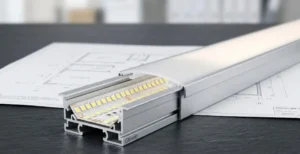
Flexible Printed Circuit 5
High-quality FPC boards feel "soft but not collapsing," showing resilience when bent. Poor cut points with collapsed or jagged edges indicate insufficient curing or dull cutting dies, which significantly increases the risk of the strip cracking or failing during long-term use.

The "Soft but Not Collapsing" Test
Pick up the strip and bend it gently.
- Good FPC (Flexible Printed Circuit): It should have a natural "rebound" or resilience. It feels sturdy despite being flexible.
- Bad FPC: If the strip feels limp and collapses immediately when bent, or if it holds the bent shape without any spring-back, it usually means the copper is too thin or the substrate material is inferior.
- Consequence: A "collapsing" FPC is prone to broken internal circuits (open circuits) after the heat of operation causes expansion and contraction.
Inspecting the Cut Points
Look closely at the copper pads where you can cut the strip.
- Clean Cuts: The edges of the PCB at the cut mark should be sharp and flat.
- Collapsed Edges: If the edge looks crushed, torn, or the silicone gel seems to "slump" over the edge, it is a bad sign.
- Reason: This often means the silicone was not fully cured when it was cut, or the cutting die was dull.
- Risk: This lack of toughness makes the strip vulnerable to tearing and moisture ingress at the connectors.
Mechanical Stress Simulation
While you cannot do a 7,000-cycle bend test in your office, you can simulate it. Twist the strip gently (do not wring it like a towel) and bend it to a 90-degree angle. Listen for cracking sounds and look for white stress marks on the silicone. High-quality modified silicone will endure this without marking; cheap epoxy or standard resin will turn white or crack.
What are the visual indicators of high-quality adhesive backing on a COB LED strip sample?
Installation failure is often not about the light dying, but the strip falling off the ceiling. In our export experience to Australia and Europe, adhesive failure is a top complaint. The backing tape is not just a sticker; it is a critical structural component.
silicone and phosphor coating 7
Visual indicators of premium adhesive include clear, sharp printing on the liner and a smooth, flat surface. Perform a "thumb-jerk" test; if the tape feels uneven or peels away from the PCB with little resistance, it suggests weak bonding or counterfeit materials.

The "Thumb Jerk" Test
This is a quick way to check the bond strength between the tape and the PCB.
- Hold the strip firmly.
- Press your thumb against the adhesive backing.
- Push or "jerk" your thumb sideways.
- Result: If the adhesive layer slides, bunches up, or easily detaches from the PCB, the bonding is weak. In a real installation, the heat of the LED will soften this glue further, causing the strip to detach from the aluminum profile.
Authenticity of the Liner
Counterfeit 3M tape is rampant in the market.
- Printing Quality: Genuine 3M VHB or 300LSE tape has crisp, sharp red text. Counterfeits often have blurry, bleeding, or slightly wrong fonts.
- Smell: Genuine tape has a mild chemical smell. Counterfeits often smell pungent or overly sweet due to cheap solvents.
Flatness and Air Pockets
Look at the adhesive from the side. It should be perfectly flat against the PCB. If you see bubbles or gaps between the tape and the circuit board, it means the tape was applied manually or without proper roller pressure. These air pockets act as insulators, trapping heat and killing the LEDs above them.
Adhesive Evaluation Guide
| Feature | Genuine/High Quality | Counterfeit/Low Quality |
|---|---|---|
| Liner Text | Crisp, sharp red text | Blurry, bleeding ink |
| Bond to PCB | Firm, difficult to rub off | Slides or peels with thumb pressure |
| Surface | Flat, no bubbles | Bubbles, wrinkles, uneven application |
| Smell | Mild solvent smell | Pungent, chemical odor |
What immediate red flags appear when the strip is powered on without using professional instruments?
Finally, plug it in. You do not need an integrating sphere to spot the most dangerous flaws. We advise our clients to look for three specific things that reveal the electrical design and material quality instantly.
concave 'fillet' shape 9
When powered on, the strip should light up instantly and simultaneously across its entire length without delay. Inspect for side shadows, which indicate thin encapsulation, and press the surface gently; high-quality gel rebounds instantly, while inferior materials leave permanent pressure marks.
1. Synchronization of Startup
When you flip the switch, watch the strip carefully.
- Good: The entire strip lights up at the exact same millisecond.
- Bad: There is a visible delay, or the strip "rolls" on, or flashes briefly before stabilizing.
- Diagnosis: This indicates poor consistency in the chips or an electrical design that is pushed to its absolute limit (over-driven). These strips are likely to fail prematurely.
2. Side Shadows (The "Cheap Look")
Look at the strip from the side, not directly from the top.
- Good: The light should appear as a solid block.
- Bad: You see dark, stripe-like shadows or can clearly see the internal structure of the chips through the side of the gel.
- Diagnosis: This means the phosphor gel layer is too thin or has poor light diffusion properties. In an aluminum profile, this will look cheap and may expose the internal wiring to view.
3. The Pressure Mark Test
With the light on (at low brightness to save your eyes), gently press your fingernail into the glowing silicone surface.
- Good: The gel rebounds immediately, and the mark disappears.
- Bad: The indentation remains visible for seconds or does not disappear at all.
- Diagnosis: This tests the elasticity and curing of the silicone. If it doesn't rebound, the gel is too soft or "under-cured." In a project, this material will attract dust that embeds permanently into the surface, ruining the clean look of the fixture.
Conclusion
Not every COB strip is built to survive a commercial project. By using these visual and tactile checks—examining the PCB layers, testing the gel rebound, and verifying the solder work—you can filter out 90% of high-risk products without spending a dollar on lab testing. Quality is often visible in the details if you know where to look.
electrical traces 10
Footnotes
- Authoritative industry body (UL) discussing safety and quality certification for LED lighting. ↩︎
- Academic research center (LRC) discussing LED system design and thermal reliability. ↩︎
- NIST laboratory description of the standard instrument used for measuring light output. ↩︎
- Official product page for 3M VHB tapes, the industry standard for LED strip adhesion. ↩︎
- General background information on flexible electronics technology. ↩︎
- Official US Department of Energy page defining LED color characteristics. ↩︎
- Major manufacturer (Dow) of optical silicone encapsulants for LED lighting. ↩︎
- UK National Physical Laboratory resource on electronics reliability and corrosion testing. ↩︎
- IPC-A-610 is the global industry standard for electronic assembly acceptance and solder joints. ↩︎
- Leading PCB software company explaining trace width and current capacity. ↩︎