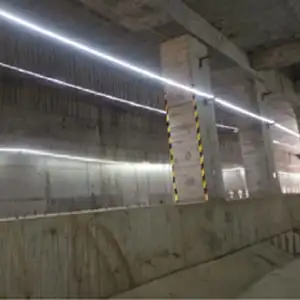
I recently quoted a commercial project where a competitor offered prices commercial project 1 40% lower than ours, causing the client to hesitate. This massive price gap usually hides risky material shortcuts that threaten installation safety. installation safety 2
To identify quality traps in low-priced COB strips, inspect the PCB copper weight for thickness below 2oz and request third-party LM-80 reports to verify lumen maintenance. Check for unbranded chips, vague binning codes, and inferior silicone that cracks under heat, as these cut costs but drastically shorten lifespan.
Let’s break down the technical red flags hidden in those tempting budget quotes so you can avoid costly replacements.
How can I verify if the PCB copper thickness is sufficient to prevent overheating in my installations?
In our Shenzhen facility, we reject any PCB under 2oz for high-density models because accumulated heat kills LEDs fast. Thin boards are invisible profit killers that compromise the entire system's thermal management.
You can verify PCB quality by measuring voltage drop across a 5-meter run; a drop exceeding 10% indicates insufficient copper. Physically measure thickness with calipers or request a UL specification sheet confirming 2oz to 3oz weight, as 1oz boards cannot dissipate the intense heat of COB arrays.
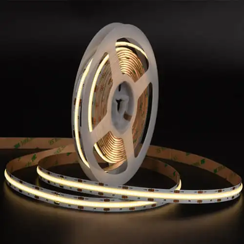
When we analyze the failures of budget COB strips sent to us by frustrated clients, the primary culprit is almost always the Printed Circuit Board (PCB). Printed Circuit Board 3 The PCB acts as the backbone of the LED strip, carrying electrical current and, more importantly, dissipating heat. COB (Chip on Board) technology packs hundreds of chips closely together—often 480 to 720 chips per meter. This high density creates a concentrated heat zone that standard PCBs simply cannot handle.
The industry standard for "economy" strips is 1 ounce (oz) of copper. While this is acceptable for low-power SMD strips, it is a death sentence for high-density COB products. In our testing labs, we have observed that 1oz copper PCBs in COB strips can reach temperatures of 80°C (176°F) within minutes of operation. High temperatures degrade the phosphor silicone and the LED chip itself, leading to a rapid drop in brightness and color shifting.
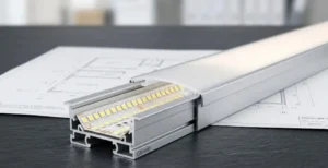
To cut costs, some suppliers use a "double-sided" PCB that actually has very thin copper plating, barely reaching 1oz in total. They might claim it is a "double-layer design," which sounds technical but effectively means nothing if the copper weight isn't there. For professional installations, especially those enclosed in aluminum profiles or coves, you must insist on a minimum of 2oz double-layer rolled annealed copper. This ensures the heat spreads evenly across the entire strip length rather than pooling at the chips.
You can perform a field test without a lab. Power up a 5-meter reel from one end. After 30 minutes, touch the strip at the powered end and the tail end. If the powered end is scorching hot while the tail end is significantly dimmer and cooler, the copper is too thin to carry the current effectively. This resistance creates heat rather than light.
PCB Copper Weight Performance Comparison
The table below illustrates how copper weight impacts the operating temperature and lifespan of a standard 10W/m COB LED strip.
| PCB Specification | Copper Weight (Total) | Temperature Rise (after 1 hr) | Voltage Voltage drop 4 Drop (5m Run) | Est. Lifespan Impact |
|---|---|---|---|---|
| Budget / Economy | 1 oz (35µm) | High (> 75°C) | > 2.5V (Significant) | Reduced by 40-50% |
| Standard Professional | 2 oz (70µm) | Moderate (55-60°C) | < 1.5V (Acceptable) | Rated Lifespan (Standard) |
| High-End / Industrial | 3 oz (105µm) | Low (< 45°C) | < 0.8V (Excellent) | Extended by 20% |
Will choosing the lowest quote result in visible color inconsistency or binning issues across different batches?
We often help clients replace "bargain" strips that look mismatched after a simple repair, destroying the project's aesthetic. Controlling MacAdam MacAdam Ellipse standard 5 ellipses is costly, so budget factories often skip this essential step.
Choosing the lowest quote often leads to poor binning, resulting in visible color shifts between rolls or future batches. Budget suppliers typically use "off-bin" chips with wide MacAdam steps (SDCM > 5), causing noticeable pink or green tints instead of a clean, consistent white light.
Color consistency is one of the most expensive aspects of LED manufacturing, and it is the first thing to go when a supplier needs to drop their price. In the professional lighting world, we use the MacAdam Ellipse standard (SDCM MacAdam Ellipse standard 6 - Standard Deviation Colour Matching) to measure how consistent a light color appears to the human eye.
When we produce our premium lines, we pay a premium to chip manufacturers for strict "binning." This means we only accept chips that fall within a 3-step MacAdam ellipse. To the human eye, all strips from this batch—and ideally future batches—will look identical.
Low-priced suppliers operate differently. To offer that rock-bottom quote, they purchase "open bin" or "mixed bin" chips. These are the leftovers that didn't make the cut for the premium brands. While they might all technically be "3000K Warm White," the reality is a visual disaster. One reel might lean towards a greenish hue, while the next one looks slightly pink or yellow.
This issue becomes a nightmare during installation. Imagine you are lighting a long corridor. You install five reels in a row. If the third reel is from a slightly different bin range (common in cheap manufacturing), you will see a distinct line where the color temperature shifts. We call this the "zebra effect."
Furthermore, budget manufacturers rarely maintain bin code records. If a driver fails or a section of strip gets damaged six months later, buying a replacement from the same low-cost supplier is a gamble. They likely cannot match the original batch, forcing you to replace the entire run to maintain consistency.
Understanding SDCM Levels and Visual Perception
The following table explains what different SDCM levels mean for your project's visual quality.
| SDCM Level | Description | Visual Experience | Typical Application |
|---|---|---|---|
| 1-Step | Laboratory Grade | No visible difference. | Color matching labs, medical. |
| 3-Step | Professional Grade | Virtually imperceptible difference. | High-end hotels, galleries, homes. |
| 5-Step | Commercial Grade | Slight differences visible upon close inspection. | General office lighting, street lights. |
| > 7-Step | Budget / Low End | Obvious color mismatch (Green/Pink tints). | Cheap DIY kits, low-cost signage. |
When we audit raw material suppliers, we use microscopes to check wire bonds, as this is a common failure point. Many budget factories swap reliable gold for cheap alloy without ever mentioning it on the datasheet.
Hidden signs of inferior components include rapid lumen depreciation within 1,000 hours and flickering caused by broken alloy bonding wires. Check for generic, unbranded chips and request a wire material analysis; reliable COB strips use 99.99% gold wire to withstand thermal expansion, while cheap alternatives use brittle copper.
The internal components of a COB strip are microscopic, making them the perfect place for suppliers to hide cost-cutting measures. The two critical components here are the LED chip size and the bonding wire material.
First, let’s talk about the bonding wire. This microscopic wire connects the LED chip to the circuit board. In our high-end products, we strictly use 99.99% pure gold wire. Gold is highly conductive and, more importantly, incredibly ductile. LED strips heat up and cool down repeatedly, causing materials to expand and contract. Gold wire flexes with this movement.
Budget suppliers frequently substitute gold with copper or silver-alloy wires. While this saves significant manufacturing costs, these metals are harder and more brittle. Over time, the thermal expansion and contraction thermal expansion 7 cause these alloy wires to snap. The result? You will see sections of your COB strip start to flicker or die out completely. This is a mechanical failure disguised as an electrical one.
Second, consider the chip size. COB strips allow manufacturers to use smaller chips because they are packed so densely. However, there is a limit. Cheap quotes often rely on undersized chips (e.g., small flip-chips) that are "overdriven." The manufacturer pushes high current through a tiny chip to achieve a high lumen count on the spec sheet.
This is a trap. While the strip might look bright initially, the tiny chips cannot handle the current density. They degrade rapidly. We have seen budget strips lose 30% of their brightness in just 1,000 hours—that is less than six months of usage in a retail store. A quality manufacturer will use larger chips and run them at a conservative current to ensure they last 50,000 hours.
Bonding Wire Material Comparison
This table outlines the differences between wire materials used in COB manufacturing.
| Wire Material | Conductivity | Ductility (Flexibility) | Corrosion Resistance | Reliability Risk |
|---|---|---|---|---|
| 99.99% Gold | Excellent | Superior | High | Very Low (Standard for Pro use) |
| Silver Alloy | Good | Moderate | Moderate | Medium (Prone to oxidation) |
| Copper | Good | Low (Brittle) | Low | High (Snaps under thermal stress) |
Does a significantly lower price indicate potential voltage drop problems for my long-run projects?
Our engineering team always calculates load limits for large commercial projects to prevent lighting failures. Ignoring voltage drop in long runs leads to dim ends and fire risks, which are common in cheap designs.
A significantly lower price often indicates thinner circuit traces that cause severe voltage drop, making long runs impossible without frequent power injection. Cheap strips may claim 24V compatibility but lack the constant current ICs or thick copper traces required to maintain uniform brightness over lengths exceeding 5 meters.
Voltage drop is a physical phenomenon Voltage drop 8 where electrical potential decreases as it travels along a wire (or trace) due to resistance. In LED strips, this manifests as the end of the strip looking significantly dimmer than the start.
When you see a quote that is surprisingly low, the manufacturer has likely compromised on the circuit design. Standard constant voltage (CV) strips rely purely on the thickness of the copper PCB to carry the current. As we discussed earlier, cheap strips use thin 1oz copper. On a 10-meter run, a cheap strip might lose 3 or 4 volts by the time the power reaches the end. A 24V strip receiving only 20V at the tail end will be noticeably dimmer.
To combat this in professional applications, we often design strips with Constant Current (CC) Integrated Circuits Constant Current 9 (ICs) embedded directly onto the PCB. These ICs regulate the current flowing through each LED segment. Even if the voltage drops from 24V to 22V, the IC ensures the LED still receives the correct amperage, maintaining perfect brightness from end to end.
Adding these ICs increases the production cost. A budget supplier will omit them entirely. They will sell you a "Long Run" strip that is just a standard strip with resistors. They might advise you to power it from both ends to hide the issue, but this doubles your wiring labor and power supply complexity.
If your project requires runs longer than 5 meters (16.4 ft) from a single power feed, you must be skeptical of low prices. A true long-run COB strip (10m, 15m, or 20m) requires complex engineering: thick copper (3oz+) or on-board IC regulation. If the price is low, you are buying a strip that will fade into darkness at the far end.
Voltage Drop Verification Checklist
- Check the Spec Sheet: Does it explicitly state "Constant Current Design" or "Built-in IC"?
- The 10% Rule: Power the strip from one end. Measure voltage at the input (e.g., 24V) and at the very end. If the end voltage is below 21.6V (more than 10% drop), the design is poor.
- Visual Test: Unroll the full length and power it. Fold the tail end back so it sits next to the head. If the difference in brightness is visible to the naked eye, the voltage drop is excessive.
Conclusion
Don't let a low sticker price fool you into costly rework and safety hazards. Verify PCB copper weight, demand binning consistency, and inspect internal components like wire bonding wire bonding 10 to ensure your project's longevity.
Footnotes
- Provides context on global energy market trends and pricing pressures in commercial lighting sectors. ↩︎
- Official government guidance on LED safety standards and efficiency for commercial and residential installations. ↩︎
- The leading industry standards body for PCB design, manufacturing, and quality control requirements. ↩︎
- Technical explanation of the physical phenomenon causing electrical potential decrease over distance. ↩︎
- General background on the scientific standard used to measure color consistency in lighting technology. ↩︎
- Authoritative definition of the color consistency standard from a leading research center. ↩︎
- Explains the physical cause of wire failure in budget strips using a reputable encyclopedia. ↩︎
- Industry leader in electrical measurement tools explaining the physical phenomenon. ↩︎
- Technical documentation from a major manufacturer regarding integrated circuits used for LED current regulation. ↩︎
- High-authority government source (NASA) on electronic component reliability and manufacturing. ↩︎