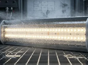
When we test new batches of COB strips in our aging racks, we often see a common issue that plagues many large-scale projects: the "fading tail" effect. You spend hours designing a beautiful cove light, only to find the last few meters look dim and yellowish compared to the start. This is voltage drop in action. At our factory, we constantly advise our engineering clients that choosing the right voltage is the single most effective way to prevent this headache before a single wire is cut.
voltage drop 1
For long-distance installations exceeding 5 meters (16.4 feet), you should almost always choose 24V COB LED strips over 12V options. 24V systems draw half the current for the same wattage, significantly reducing resistance and voltage drop, which ensures consistent brightness and color uniformity across longer runs.
In this guide, we will break down the technical reasons behind this choice and how to calculate the perfect setup for your project.
What is the maximum run length I can achieve with 24V COB strips?
In our experience supplying large commercial fit-outs, one of the most frequent questions we receive from contractors is about the maximum continuous length they can run without extra wiring. It is frustrating to design a 10-meter room perimeter only to find out standard strips require a new power feed every 5 meters. We have developed specific PCB designs to push these limits.
A standard 24V COB LED strip can typically achieve a maximum continuous run of 10 meters (32.8 feet) without visible voltage drop. However, by using specialized Constant Current (IC) designs, we can extend this maximum run length up to 20 meters (65.6 feet) while maintaining perfect uniformity from end to end.
Understanding the Limits of Voltage
When we engineer LED strips, we are fighting against the internal resistance of the flexible PCB (Printed Circuit Board). Every meter of copper trace adds resistance. In a 12V system, the current is doubled compared to a 24V system to achieve the same wattage. Higher current moving through that resistance creates heat and results in a significant voltage drop.
By switching to 24V, we lower the current. This allows the voltage to travel further down the strip before it drops below the threshold where the human eye can detect dimming.
Standard Voltage vs. Constant Current (CC)
For our project-grade clients, we offer two distinct types of 24V solutions. Understanding the difference is key to planning your wiring:
- Constant Voltage (Standard): These are the most common. Resistors regulate the current. They are cost-effective but generally limited to 5 meters (12V) or 10 meters (24V).
- Constant Current (CC): These strips have integrated circuits (ICs) on the PCB. The ICs ensure that every LED receives the exact same current, regardless of minor voltage fluctuations. This technology allows us to produce strips that run 15 to 20 meters powered from just one end.
The Trade-off: Cutting Increments
While 24V allows for longer runs, there is a physical trade-off regarding how precisely you can cut the strip. Because 24V circuits require more LEDs in series, the cutting points are further apart.
Comparison of Specifications
Here is a breakdown of how voltage impacts your installation parameters:
| Feature | 12V COB Strip | 24V COB Strip | 24V Constant Current Strip |
|---|---|---|---|
| Max Run (Single Feed) | 5 Meters (16.4 ft) | 10 Meters (32.8 ft) | Up to 20 Meters (65.6 ft) |
| Current Draw (per 100W) | ~8.3 Amps | ~4.1 Amps | ~4.1 Amps |
| Cutting Unit Length | ~25mm (1 inch) | ~50mm (2 inches) | ~100mm (4 inches) |
| Voltage Drop Risk | High | Low | Very Low |
| Best Application | Furniture, Shelves, Vehicles | Cove Lighting, Ceilings | Long Corridors, Facades |
For most architectural projects, the 50mm cutting increment of 24V is acceptable, and the benefit of longer runs far outweighs the precision loss.
Should I consider 48V strips for extremely long runs to minimize wiring?
We recently worked on a warehouse retrofit where the cable trays were already overflowing, and the installer was desperate to minimize the amount of copper wire used. In scenarios like this, even 24V might not be enough. While less common in residential settings, high-voltage DC systems are becoming a staple in our industrial product lines.
blue LED chip 2
You should consider 48V strips for extremely long runs exceeding 20 meters or for large-scale commercial projects where minimizing driver quantity and cabling gauge is critical. 48V systems allow for runs up to 50 meters (164 feet) on a single power feed, drastically simplifying installation labor.

The Efficiency of High Voltage
Just as power grids use high voltage to transmit electricity across cities, 48V LED strips use higher voltage to push power across long architectural lines. When we manufacture 48V strips, we are essentially quadrupling the voltage compared to 12V, which means the current is divided by four.
This massive reduction in current has two major benefits for your project:
- Thinner Wires: You can use thinner, less expensive gauge wire (like 20AWG or 22AWG) even for very long lead wires between the power supply and the strip.
- Fewer Power Supplies: Instead of hiding a driver every 10 meters, you can have one centralized, high-wattage driver powering a massive 50-meter perimeter.
Safety and Certification Considerations
However, moving to 48V requires a shift in safety thinking. In many regions, anything below 60V DC is still considered "Safety Extra Low Voltage" (SELV), which means you generally do not need a licensed electrician to handle the low-voltage side. However, 48V is closer to that limit.
- Touch Safety: While 12V and 24V are completely safe to touch, 48V can cause a mild shock if your hands are wet or if the skin is broken, though it is generally safe.
- Component Availability: 48V power supplies and controllers are less commonly found at local hardware stores compared to 12V/24V components. You usually need to source these from specialized B2B suppliers like us.
When to Choose Which Voltage
To help you decide, we use this simple decision matrix for our clients:
- 0 - 5 Meters: Use 12V. (Best for tight cutting and small batteries).
- 5 - 20 Meters: Use 24V. (The industry standard for homes and offices).
- 20 - 50 Meters: Use 48V. (Ideal for warehouses, exterior building outlines, and long hallways).
Critical Thinking: The Maintenance Factor
One downside we point out to buyers is maintenance. If a section of a 48V strip fails, finding a replacement quickly can be harder than finding a standard 24V strip. Furthermore, 48V strips often have cutting increments of 10cm or more, making them poor choices for intricate joinery or cabinets.
How does voltage drop affect the brightness uniformity of my installation?
There is nothing worse for a lighting designer than turning on a system and seeing a "gradient" effect where the light starts bright white and ends in a dim orange hue. We see this often when clients try to push specifications without calculating resistance. It is not just about brightness; it is about the quality of light.
licensed electrician 4
Voltage drop causes a visible decrease in brightness and a shift in color temperature towards the red spectrum at the end of the LED strip. This occurs because the voltage available to the LEDs decreases as it travels away from the power source, preventing the furthest chips from operating at full capacity.

The Physics of the "Red Shift"
Why does the color change? In a white LED strip, the light is created by a blue LED chip exciting a yellow phosphor coating. The blue chip requires a specific forward voltage (usually around 2.8V to 3.2V) to function correctly.
When voltage drop occurs, the energy reaching the blue chip drops. As the blue light intensity fades, the phosphor's yellowish tone becomes more dominant, and the overall light appears warmer and dimmer. In RGB strips, this is even more obvious: the white mixed light will turn pink or red at the end because the red LEDs require less voltage to light up than the green or blue ones.
20AWG 6
Calculating the Drop
We recommend keeping voltage drop below 3% for high-end architectural projects, though up to 10% is often acceptable for general cove lighting where the light source is hidden.
Here is a simplified look at how wire gauge (thickness) impacts drop over distance. This table assumes a 100W load at 24V:
power grids 7
| Wire Gauge (AWG) | Distance: 5 Meters | Distance: 10 Meters | Distance: 20 Meters |
|---|---|---|---|
| 18 AWG | ~1.5% Drop (Excellent) | ~3.0% Drop (Good) | ~6.0% Drop (Acceptable) |
| 20 AWG | ~2.5% Drop (Good) | ~5.0% Drop (Acceptable) | ~10% Drop (Visible Dimming) |
| 22 AWG | ~4.0% Drop (Acceptable) | ~8.0% Drop (Visible) | ~16% Drop (Failure) |
The Role of PCB Thickness
As a manufacturer, one way we combat this is by using thicker copper in our PCBs. Standard market strips use 2oz (ounce) copper. For our high-performance "Long Run" series, we often upgrade to 3oz or 4oz copper.
Thicker copper acts like a wider highway for the electrons, reducing resistance. When you are sourcing products, always ask your supplier about the PCB copper weight. If they cannot tell you, it is likely a standard 2oz product that will suffer from higher voltage drop.
integrated circuits (ICs) 8
Visualizing the Failure
If you ignore these calculations, the result is uneven lighting. In a cove, this looks like a shadow in the corner. In direct-view applications (where you can see the strip), it looks like a defect. For COB strips, which are prized for their seamless line of light, voltage drop ruins the very effect you are paying for by creating a faded, non-continuous look.
Do I need to inject power at both ends for runs over 10 meters?
When we assist with troubleshooting on-site, the solution to dim lighting is rarely "buy new lights." It is almost always about how the power is delivered. Many installers assume that plugging power into one end is enough, but electricity behaves like water pressure in a hose—it gets weaker the further it travels.
internal resistance 9
Yes, for runs exceeding 10 meters, you generally need to inject power at both ends or at intermediate points to ensure uniform brightness. This technique, known as power injection, provides fresh voltage to the far end of the strip, effectively neutralizing voltage drop and balancing the light output.
Methods of Power Injection
There are three main ways we recommend wiring your strips to handle long distances. Choosing the right one depends on your access to the installation area.
1. Double-Ended Feed (The Standard Solution)
This is the most common method for runs between 10 and 20 meters. You run a wire from the power supply to the start of the strip and a second wire from the same power supply to the end of the strip.
- Pros: Simple to understand; doubles the effective max run length.
- Cons: You need to run a return wire parallel to the strip.
2. Middle Injection (Center Feed)
Instead of powering the ends, you connect the power supply to the exact middle of the strip run.
- Pros: Effectively cuts the run length in half. A 20-meter strip becomes two 10-meter strips moving in opposite directions.
- Cons: Requires cutting the strip or soldering wires in the middle, which can be messy during installation.
3. Parallel Injection (For Ultra-Long Runs)
For massive perimeters (e.g., 50 meters), you run a thick "trunk" cable (like 14AWG or 12AWG) alongside the LED strip. Every 5 or 10 meters, you tap into this trunk line and connect it to the LED strip pads.
Connectors vs. Soldering
We often see issues arise at the connection points. While soldering is always the most reliable method, we know it is difficult to do on a ladder.
- Soldering: Provides the lowest resistance and most secure connection. Essential for high-current setups.
- Quick Connectors: We offer transparent "hippocampus" style connectors. These are great for speed, but they add resistance. If you use connectors for power injection, ensure they are rated for the current you are pushing.
Troubleshooting Guide: When to Inject Power
Use this table to diagnose if your current setup needs more power points:
| Symptom | Cause | Solution |
|---|---|---|
| End of strip is yellow/orange | Voltage Drop | Add power feed to the end (Double-Ended Feed). |
| Strip is hot at the start, dim at end | Overloaded Series Run | Split strip into sections; power each section independently. |
| Flickering at high brightness | Insufficient PSU Power | Upgrade Power Supply Unit (Wattage is too low). |
| Colors are mismatched (RGB) | Voltage Drop (Red dominant) | Use thicker gauge wire for the main feed or inject power. |
The "Home Run" Wiring Strategy
For the best reliability, we recommend the "Home Run" method. This means every 5-10 meter section of LED strip has its own dedicated wire running back to the power supply. Do not daisy-chain strips (connecting the end of strip A to the start of strip B) indefinitely. Daisy-chaining forces the current for the entire run to pass through the thin PCB of the first strip, which creates a bottleneck and excessive heat.
Conclusion
Choosing between 12V and 24V is not just a technical preference; it is the difference between a professional-grade installation and one that looks amateurish after a few months. For any run over 5 meters, 24V is the clear winner, offering better efficiency, lower voltage drop, and easier wiring. By combining the right voltage with smart power injection strategies and correct wire gauges, you ensure your COB strips deliver that seamless, solid beam of light they were designed for.
Footnotes
- Authoritative explanation of voltage drop from a major test tool manufacturer. ↩︎
- Documentation from the pioneer manufacturer of blue LED technology. ↩︎
- Government guide explaining color temperature and light appearance. ↩︎
- Government safety regulations regarding electrical work and qualifications. ↩︎
- Official definition from the International Electrotechnical Commission (IEC). ↩︎
- General reference for the American Wire Gauge standard. ↩︎
- Government source explaining high voltage transmission efficiency. ↩︎
- Major manufacturer of LED driver ICs explaining the technology. ↩︎
- Educational resource defining resistance and resistivity in physics. ↩︎
- Link to the global trade association and standards body for PCBs. ↩︎