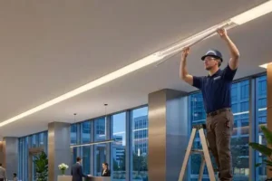
Every week on production line, we run quality checks on thousands of meters of LED strip lights, and the question we hear most from overseas buyers is deceptively simple: how do these things actually work P-type layer 1? The problem is, most explanations stop at "electricity goes in, light comes out." That leaves contractors guessing about voltage, color consistency, and why their 10-meter run dims at the end. The real gap is not in understanding the basic science—it is in understanding what separates a strip that lasts 50,000 hours from one that fails in six months.
LED strip lights work through electroluminescence: low-voltage DC power flows through semiconductor chips mounted on a flexible circuit board, causing electrons to recombine with holes and release photons as visible light. Resistors on each segment regulate current for safe, stable operation.
Below, we break down the internal components, color consistency, voltage drop 2 solutions, and waterproof protection principles so you can specify and install LED strips with confidence.
How do the internal components of my LED strip convert electricity into light?
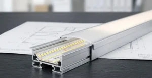
When we calibrate our SMD placement machines 3 each morning, we are reminded that every component on the strip has a job—and if even one fails, the whole segment goes dark. Many buyers focus only on the LED chip, but they overlook the resistors, copper traces, and PCB substrate that make stable light output possible.
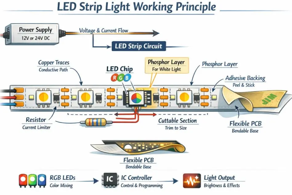
Inside an LED strip, surface-mount LED chips sit on a flexible copper PCB. When DC voltage is applied, current flows through resistors into each chip's semiconductor junction, where electrons recombine with holes to emit photons—producing visible light without a heated filament.
The Core Components on the Strip
Let's walk through each part. A typical LED strip has five main components working together.
| Component | Function | Why It Matters |
|---|---|---|
| LED Chip (e.g., SMD 2835, 5050) | Converts electrical energy into light via electroluminescence 5 | Determines brightness, color, and efficiency |
| Flexible PCB (FPCB) | Provides the physical base and copper traces for electrical conductivity | Copper thickness affects current capacity and heat dissipation |
| Resistor | Limits current to each LED group to prevent overcurrent | Without it, LEDs burn out quickly |
| Adhesive Backing (3M tape) | Allows mounting to surfaces | Quality adhesive prevents peeling in warm environments |
| Protective Coating (silicone/epoxy) | Shields components from moisture and dust | Determines IP rating and outdoor suitability |
How Electroluminescence Works in Practice
The LED chip itself is a tiny semiconductor. semiconductor chips 6 It has two layers: a P-type layer (positive, with "holes") and an N-type layer 7 (negative, with excess electrons). When you apply forward voltage —say 3V across a single white LED—electrons from the N-side cross into the P-side. They fall into holes. Each time an electron fills a hole, it releases a small packet of energy as a photon. That is light.
No filament heats up. No gas ionizes. The process is direct. This is why LEDs convert 80–90% of input energy into light, compared to about 10% for incandescent bulbs.
The Circuit Design: Series and Parallel
On a 12V strip, LEDs are wired in groups of three in series. Each group has one resistor. The three LEDs share the 12V supply: roughly 3V per LED, with the resistor absorbing any excess voltage to keep current steady at around 20mA per chip.
These groups then connect in parallel across the length of the strip. This is why you can cut at marked points without killing the rest of the strip—each group is an independent circuit.
Here is a quick comparison of common LED chip types we use:
| LED Chip Type | Size (mm) | Typical Lumens/m | Best Use Case |
|---|---|---|---|
| SMD 3528 | 3.5 × 2.8 | 300–500 | Accent lighting, signage |
| SMD 5050 | 5.0 × 5.0 | 800–1,200 | RGB color mixing, general lighting |
| SMD 2835 | 2.8 × 3.5 | 1,200–1,800 | High-output task and architectural lighting |
| COB (Chip-on-Board) | Continuous | 1,500–2,200 | Seamless, dot-free linear lighting |
Our engineers always remind buyers: watts alone do not tell you brightness. A cheap 14W/m strip might output only 600 lm/m, while a well-designed 14W/m 2835 strip can hit 1,500 lm/m. Always check lumens per meter.
Why Current Control Is the Real Story
Here is my personal take. Everyone knows LEDs emit light when current passes through a chip. That part is simple. But the real difference between a good strip and a bad one is how stable that current stays. If the resistor value is wrong, or the copper traces are too thin, current fluctuates. You get brightness variation, color shifting, and a lifespan that drops from 50,000 hours to maybe 15,000. So when we evaluate a strip, we never just ask "does it light up?" We ask: "Can it light up the same way in a freezing German warehouse and a hot Australian rooftop, five years from now?" That is the real test.
How can I ensure my LED strips maintain perfect color consistency across different production batches?
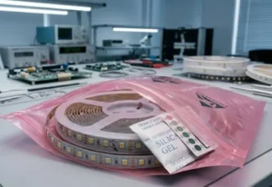
One of the biggest headaches we see from distributors like Roy in Australia is this: the first batch of warm white strips looks perfect, but the second batch arrives slightly pinkish. The project is half-installed. The client is furious. This problem ruins reputations—and it is far more common than most people think.
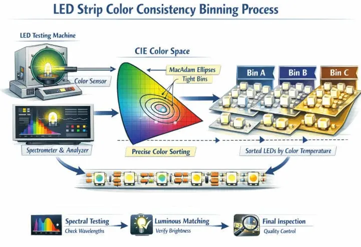
Color consistency across batches depends on strict LED chip binning, where manufacturers sort chips by precise color temperature (CCT) and brightness (lumens) before assembly. Specifying tight MacAdam ellipse bins—ideally 3-step or tighter—and partnering with a supplier who enforces incoming QC ensures visual uniformity across every reel.
What Is Binning and Why Does It Matter?
LED chips come off the wafer with natural variation. Not every chip hits exactly 3000K warm white. Some land at 2950K, others at 3100K. The human eye can detect surprisingly small shifts—about 50–100K difference side by side.
Binning is the sorting process. After fabrication, LED chips are tested and grouped by color coordinates, brightness, and forward voltage. The tighter the bin, the more consistent the final product.
The industry standard for measuring color consistency is the MacAdam ellipse 9. Here is what the step numbers mean:
| MacAdam Step | Perceptible Difference | Typical Application |
|---|---|---|
| 1-step | Indistinguishable to human eye | Laboratory reference |
| 3-step | Barely noticeable, even side by side | Architectural, hospitality, high-end retail |
| 5-step | Noticeable when strips are adjacent | General commercial, signage |
| 7-step | Clearly visible difference | Budget residential, temporary installations |
For project-grade work, we always recommend 3-step MacAdam bins. Most of our German and Australian clients spec this as a minimum requirement.
The Supply Chain Challenge
Here is the hard truth. Even if your supplier promises 3-step binning, the reality depends on their relationship with the chip manufacturer. Large chip makers like Cree, Samsung, or Nationstar produce millions of LEDs per batch. If your strip supplier buys chips from spot markets or brokers, they get random bins mixed together. Result: inconsistent strips.
At our facility, we lock in specific bin codes with our chip suppliers at the purchase order level. We record bin codes for every reel we produce. If a client reorders six months later, we can match the original bin—or at least get within the same 3-step range.
Practical Steps for Buyers
- Specify MacAdam step in your purchase order. Do not assume your supplier knows your tolerance.
- Request bin code traceability. A good supplier will document which chip bin went onto which reel.
- Order extra stock for future repairs. Even with perfect binning, LED phosphor ages over time. Matching a five-year-old installation with brand-new strip is nearly impossible.
- Test samples under your actual lighting conditions. Fluorescent office light hides CCT differences that daylight reveals.
When we work with design firms specifying strips for hotels or museums, we sometimes run pilot batches for sign-off before mass production. That small upfront investment prevents costly rework on-site.
How do I solve the problem of voltage drop in my long-run LED strip installations?
In our experience exporting to Australian contractors, this is the single most common installation complaint: "The strip looks great at the start, but it gets dimmer and slightly off-color at the far end." That is voltage drop. And if you are running anything longer than 5 meters on 12V DC, you will hit it.
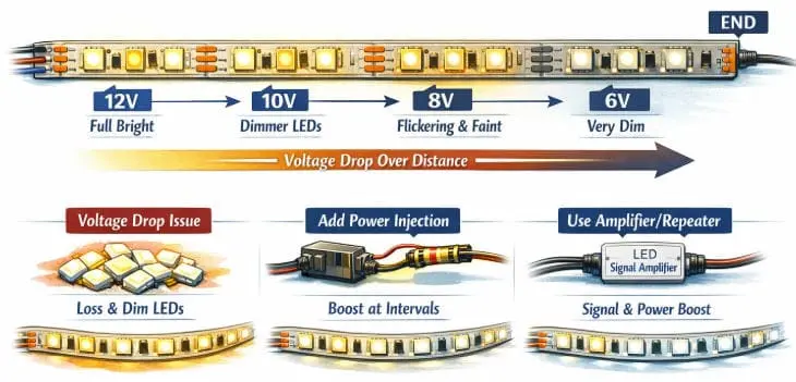
Voltage drop occurs because the copper traces on the flexible PCB have resistance. As current travels along the strip, voltage decreases progressively, causing LEDs at the far end to receive less power. Solutions include using 24V or 48V strips, injecting power at multiple points, using thicker copper PCBs, and keeping individual runs within recommended lengths.
Understanding Why Voltage Drop Happens
Copper is a great conductor, but it is not perfect. The thin copper traces on a flexible PCB—typically 1oz or 2oz copper—have measurable resistance. flexible circuit board 10 The longer the strip, the more resistance the current encounters. By Ohm's law (V = I × R), more resistance means more voltage lost as heat in the traces before it reaches the LEDs at the end.
At 12V, a 5-meter run of 60 LEDs/m drawing 14W/m already pushes the copper traces hard. By the last meter, voltage might drop from 12V to 10.5V. Those LEDs receive 12% less voltage. They dim. If it is an RGB strip, the color shifts because each color LED responds differently to reduced voltage.
Practical Solutions
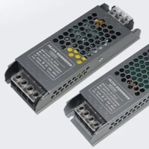
Switch to 24V or 48V strips. Higher voltage means lower current for the same wattage. Lower current means less voltage drop across the same resistance. A 24V strip can comfortably run 10 meters. A 48V strip can reach 15–20 meters in some configurations.
Power injection. Feed power to the strip at multiple points—both ends, or every 5 meters—instead of from one end only. This is the most reliable method for long commercial runs. Our team provides wiring diagrams specific to each project layout.
Use heavier copper PCBs. Standard strips use 1oz copper. We offer 2oz and 3oz copper options for high-power and long-run projects. Thicker copper means lower trace resistance.
Keep individual runs short. For a 30-meter cove lighting project, do not daisy-chain one continuous strip. Break it into segments, each powered independently or with parallel power feeds.
Here is a quick reference:
| Strip Voltage | Max Recommended Single Run | Typical Voltage Drop at Max Run | Best Fix for Longer Runs |
|---|---|---|---|
| 12V DC | 5 meters | ~10–15% | Power injection every 5m |
| 24V DC | 10 meters | ~8–12% | Power injection every 10m |
| 48V DC | 15–20 meters | ~5–8% | Single run often sufficient |
| AC Mains (230V) | 50–100 meters | Minimal | Built-in rectifier per segment |
A Real-World Example
A contractor in Melbourne needed 25 meters of warm white strip for a continuous cove in a restaurant. They initially ordered 12V strip and wired it from one end. The last 10 meters were visibly dimmer. We replaced it with 24V strip on 2oz copper PCB and added power injection at 0m, 12m, and 25m. The result was perfectly even light across the entire run. The additional cost for thicker copper and extra wiring was minor compared to the labor of ripping out and reinstalling.
If you are planning any installation over 5 meters, talk to your supplier about voltage and injection points before you order. It is much cheaper to plan it right than to fix it after the ceiling is closed up.
What is the working principle behind the IP-rated protection on my outdoor LED strips?
When we test our outdoor LED strips in our IP-rating lab, we simulate years of rain, dust, and UV exposure in a matter of weeks. Contractors in Australia and Germany regularly ask us: "What actually makes a strip waterproof?" The answer is not just a silicone sleeve—it is a layered engineering approach that most buyers never see.
IP (Ingress Protection) ratings on LED strips indicate the level of physical barrier against solid particles and moisture. Protection is achieved through silicone coatings (IP65), silicone sleeve extrusions (IP67), or fully potted encapsulation in silicone or resin (IP68), each creating a sealed barrier that prevents water and dust from reaching the electrical components on the PCB.
Decoding the IP Rating System
The IP code has two digits. The first digit (0–6) rates protection against solids like dust. The second digit (0–9) rates protection against water. For LED strips, the most common ratings are IP20, IP54, IP65, IP67, and IP68.
| IP Rating | Solid Protection | Water Protection | Typical LED Strip Construction | Common Use |
|---|---|---|---|---|
| IP20 | Touch-safe | None | Bare PCB, no coating | Indoor coves, under cabinets |
| IP54 | Dust-resistant | Splash-proof | Light nano-coating on components | Sheltered outdoor, bathroom mirrors |
| IP65 | Dust-tight | Low-pressure water jets | Silicone or epoxy coating over top surface | Outdoor facades, signage |
| IP67 | Dust-tight | Temporary immersion (up to 1m) | Silicone sleeve extrusion around entire strip | Garden paths, pool surrounds |
| IP68 | Dust-tight | Continuous submersion (beyond 1m) | Full potting in silicone within a rigid or flexible tube | Underwater, fountains |
How Each Protection Method Works
IP65 – Surface Coating. A layer of silicone or epoxy is applied directly over the LEDs and PCB surface. This keeps rain and splashes out. However, the back and edges of the PCB may still be exposed. It works well for vertical installations where water runs off quickly.
IP67 – Sleeve Extrusion. The entire strip is inserted into a silicone tube. Both ends are sealed with end caps and silicone adhesive. Water cannot enter from any direction. The downside is that the sleeve adds thickness and can trap heat, so thermal management becomes more important.
IP68 – Full Potting. The strip is placed inside a tube and the interior is filled with clear or translucent silicone resin. There is zero air gap. Even under continuous water pressure, moisture cannot reach the PCB. This is the method we use for underwater fountain projects and pool lighting.
Material Quality Matters More Than the Number
Here is something most buyers miss. Two strips can both claim IP67, but one fails after six months outdoors while the other lasts five years. The difference is material quality. Cheap PVC sleeves yellow and crack under UV exposure. Low-grade silicone becomes brittle in freezing temperatures.
We use UV-stabilized silicone for all our outdoor products. It maintains flexibility from -40°C to +80°C and resists yellowing for years. Our end caps are bonded with industrial-grade silicone adhesive, not just friction-fit.
We also perform accelerated aging tests: 1,000 hours of UV exposure, salt spray testing for coastal installations, and thermal cycling between -20°C and +60°C. These tests weed out material failures before the product ships.
Choosing the Right IP for Your Project
If the strip is fully sheltered under an eave, IP54 may suffice. If it faces direct rain, specify IP65 minimum. For ground-level installations where water can pool, go IP67. And for anything submerged—even temporarily—IP68 is non-negotiable.
One more tip: always check how the connectors and power feed points are sealed. The strip itself might be IP67, but if the solder joint to the power cable is exposed, water enters there first. We supply pre-sealed connectors and heat-shrink junction kits for exactly this reason.
Conclusion
LED strip lights are simple in concept but complex in execution. From electroluminescence to binning, voltage drop to IP protection, every detail matters for a lasting installation. If you need project-grade strips with guaranteed consistency and technical support, reach out to us for more details.
Footnotes
- Replaced with the Simple English Wikipedia page for 'P-type semiconductor' for a clear and authoritative explanation. ↩︎
- Replaced with the Wikipedia page for 'Voltage drop' for an authoritative explanation. ↩︎
- Replaced with the Wikipedia page for 'Pick-and-place machine', which is a common term for SMD placement machines and an authoritative source. ↩︎
- Explains the LED chip as the semiconductor device at the core of LED lighting. ↩︎
- Explains the optical and electrical phenomenon of light emission from a material. ↩︎
- Defines semiconductor chips as fundamental components for modern electronics and their function. ↩︎
- Replaced with the Wikipedia page for 'N-type semiconductor' for an authoritative explanation. ↩︎
- Explains forward voltage as the voltage drop across a conducting diode in the forward direction. ↩︎
- Replaced with the Wikipedia page for 'MacAdam ellipse' for an authoritative explanation. ↩︎
- Describes flexible PCBs as bendable substrates for electronic components, enabling compact designs. ↩︎