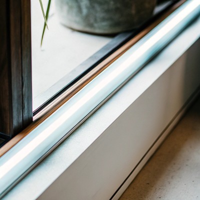
When we help our clients design lighting for custom joinery, the most common frustration they face is trying to fit standard lighting into extremely narrow grooves. This mismatch often forces installers to damage the strip or skip the diffuser, ruining the sleek, finished look you originally planned. If the light source doesn't fit perfectly, the entire architectural effect is compromised.
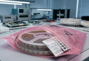
To choose the best slim COB LED strip, prioritize the profile’s internal depth over width to accommodate the strip and diffuser. Select 24V options for longer runs to minimize voltage drop, and ensure a density of at least 384 LEDs/m for seamless, dot-free illumination in shallow channels.
Here is a breakdown of the specific dimensions and technical factors you must verify before ordering your next batch of slim lights.
How can I determine the right PCB width for my ultra-slim aluminum profiles?
In our factory testing lab, we frequently see customers attempt to force standard strips into custom millwork, leading to adhesion failure and overheating. This usually happens because the design specifications focused on the wrong measurements, wasting both time and valuable materials.
Measure the clear internal width of your aluminum profile, not the external dimensions. Choose a PCB width at least 1-2mm narrower than this internal space to allow for easier installation and prevent the strip from buckling or peeling off the heat sink surface due to friction.

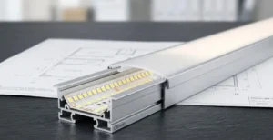
When selecting the correct PCB (Printed Circuit Board 1) width for ultra-slim profiles, precision is non-negotiable. Many project managers make the mistake of looking at the external width of the aluminum channel. For example, a profile might be marketed as "8mm slim," but that often refers to the outer edge. The internal channel—where the LED strip actually sits—might only be 5mm or 6mm wide due to the thickness of the aluminum walls.
The Internal Clearance Rule
We always recommend leaving a "breathing room" or tolerance gap. If your internal channel width is exactly 5mm, do not buy a 5mm wide strip. The installation will be incredibly difficult; the adhesive tape on the back may bunch up, or the strip might twist. Instead, you should source a 3mm or 4mm COB strip. This small gap allows for thermal expansion 2 and ensures the strip lays perfectly flat against the metal, which is critical for heat transfer.
Watch Out for Height
While width is the most obvious dimension, height is the silent killer of slim installations. We have seen countless projects where the strip fits the width, but once the wire is soldered onto the pads, the connection point becomes too tall. This prevents the plastic diffuser cover from snapping shut.
Standard COB strips are generally low profile (around 1.6mm to 2mm). However, if you are using a profile with a depth of only 4mm, a clumsy solder joint or a bulky connector clip will block the lens. For these ultra-tight spaces, we advise soldering wires directly to the PCB pads at our factory rather than using clip-on connectors, which add significant bulk.
Common Slim PCB Standards
To help you navigate the market, here are the common widths we produce for specific applications:
| PCB Width | Typical Application | Max Power Recommendation |
|---|---|---|
| 2.7mm / 3mm | Extremely thin silicone neon tubes, jewelry display edges | < 6W per meter |
| 4mm | Shallow joinery grooves, under-shelf lighting | < 8W per meter |
| 5mm | Standard slim aluminum profiles, cove lighting | < 10W per meter |
| 8mm - 10mm | Standard architectural profiles (Not "Ultra-Slim") | 10W - 15W per meter |
Will a thinner COB LED strip maintain color consistency across my entire project?
When we source phosphors for our high-end product lines, we prioritize binning accuracy above almost everything else. Inconsistent color temperatures or visible dimming at the end of a shelf can completely ruin the visual flow of a high-end retail fit-out or luxury kitchen.
Thinner strips can maintain excellent color consistency if they use high-quality strictly binned LED chips. However, voltage drop is a higher risk in narrow PCBs, which can cause color shifting at the end of the run. Using 24V or dual-ended power injection solves this common issue.
Maintaining color consistency in ultra-slim strips is a challenge involving both physics and manufacturing quality. When you reduce the width of a PCB from 10mm to 3mm, you are physically removing copper material. Copper is the highway that carries electricity. A narrower highway means more resistance, and more resistance leads to voltage drop 3.
The Physics of Voltage Drop and Color
As voltage drops along a long run of LED tape, the current reaching the furthest LEDs decreases. In standard SMD LEDs, this just creates dimming. However, in modern COB strips, significant voltage drop can sometimes cause a slight shift in color temperature (CCT) 4, making the end of the strip look warmer or pinker than the start.
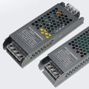
For ultra-slim installations, we strongly advise against using 12V systems for any run longer than 2 meters. A 12V current is double that of a 24V system for the same wattage, which generates more heat and resistance in those thin copper traces. By switching to 24V, you reduce the current load, allowing the thin 3mm or 4mm PCB to carry power more efficiently without noticeable color deviation.
The Importance of Binning
Beyond voltage, the manufacturing "binning" process determines the base color accuracy. Even with a slim strip, you should demand a MacAdam Ellipse step 5 of 3 or lower (SDCM < 3). This ensures that if you buy 50 meters of strip today and another 20 meters next month for the same project, the white light will look identical.
Troubleshooting Color Issues in Slim Strips
If you are planning a large installation, consider these factors:
| Factor | Impact on Slim Strips | Solution |
|---|---|---|
| Voltage | High impact. 12V causes faster drop on narrow PCBs. | Use 24V DC for all slim runs over 1m. |
| Copper Weight | Thinner PCBs often have less copper (1oz vs 2oz). | Ask suppliers for 2oz copper PCBs even on 5mm widths. |
| Power Feed | Resistance builds up quickly. | Feed power from both ends for runs > 5m. |
Visual Uniformity
The beauty of COB technology is the phosphor layer that covers the chips. This layer acts as a built-in diffuser. In slim profiles, this is vital because you often cannot fit a thick plastic diffuser on top. A high-quality COB strip ensures that even if the profile is only 3mm deep, you will see a solid line of light rather than individual dots, maintaining the color integrity across the reflection.
How do I ensure my slim LED strips meet the heat dissipation requirements of tight spaces?
Our engineering team always warns clients that heat is the number one killer of LEDs, regardless of the brand. Ignoring thermal management in enclosed cabinets or narrow channels inevitably leads to premature dimming and eventual failure of the lighting system.
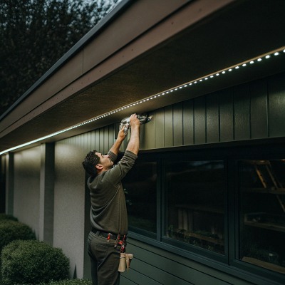
Slim strips in tight spaces require aluminum profiles to act as heat sinks, as air cooling is minimal. Avoid overpowering small profiles; stick to lower wattage (under 10W/m) for ultra-slim setups to keep operating temperatures safe and ensure the longevity of the phosphor coating.
Heat dissipation is the most critical technical constraint when working with ultra-slim lighting. When we design high-power LED strips, we rely on the surface area of the PCB and the aluminum substrate to pull heat away from the chips. In a 3mm or 4mm wide strip, that surface area is drastically reduced.
The Mass-to-Power Ratio
There is a direct relationship between the amount of aluminum in your profile and the amount of power (wattage) you can safely run. A tiny aluminum channel that is 5mm wide and 5mm deep has very little thermal mass. If you install a high-output 15W/meter strip into that channel, the aluminum will quickly become saturated with heat. Since the heat cannot escape into the surrounding wood or plaster fast enough, it reflects back into the LED strip.
Overheating causes the phosphor gel in COB strips to yellow and crack over time, which permanently alters the color of the light and reduces brightness.
Safe Wattage Guidelines
For slim installations, "less is more." You rarely need high-power lighting for accent, shelf, or cabinet applications. We recommend the following power limits based on the installation environment:
| Installation Type | Airflow | Recommended Max Power |
|---|---|---|
| Open Surface | Good | Up to 12W/meter |
| Aluminum Profile (Surface) | Moderate | Up to 10W/meter |
| Recessed in Wood/Drywall | Poor | Max 6W - 8W/meter |
| Silicone Tube / IP67 | Very Poor | Max 5W/meter |
Thermal Tape Matters
Because the contact area is so small on a slim strip, the quality of the double-sided tape on the back is paramount. We use high-grade thermal conductive tape 6 (often red or blue liner variants like 3M VHB or similar industrial grades) that facilitates heat transfer from the PCB to the aluminum.
If the tape fails and the strip detaches even slightly, an air gap forms. Air is an insulator. That section of the strip will immediately overheat and fail. Before installing, ensure the aluminum surface is cleaned with alcohol to remove oils or dust, ensuring a 100% bond for thermal transfer.
Can I customize the cutting lengths of slim COB strips to fit my specific architectural dimensions?
We frequently customize production runs for contractors who need exact lengths for joinery, because standard rolls rarely fit perfectly. Cutting mistakes on-site often leave ugly dark spots at the corners, which compromises the seamless effect designers strive for.
Yes, slim COB strips are highly customizable with cutting points as frequent as every 10mm to 25mm. You can cut them at designated copper pads using sharp scissors, but soldering wires onto ultra-narrow pads requires precision or pre-ordered custom leads from your supplier.
One of the greatest advantages of COB technology is the incredibly short cutting unit (or cutting pitch). Traditional SMD LED strips might have cutting points every 50mm or 100mm. If your cabinet shelf is 480mm wide and your cutting unit is 100mm, you have to cut the strip at 400mm, leaving 40mm of darkness on both ends.
Understanding Cut Points
Slim COB strips typically have cutting points ranging from 10mm to 25mm. This allows you to fill almost the entirely available space. For example, with a 12.5mm cut unit, you can cut a strip to 475mm for that 480mm shelf, leaving virtually no dark spots.
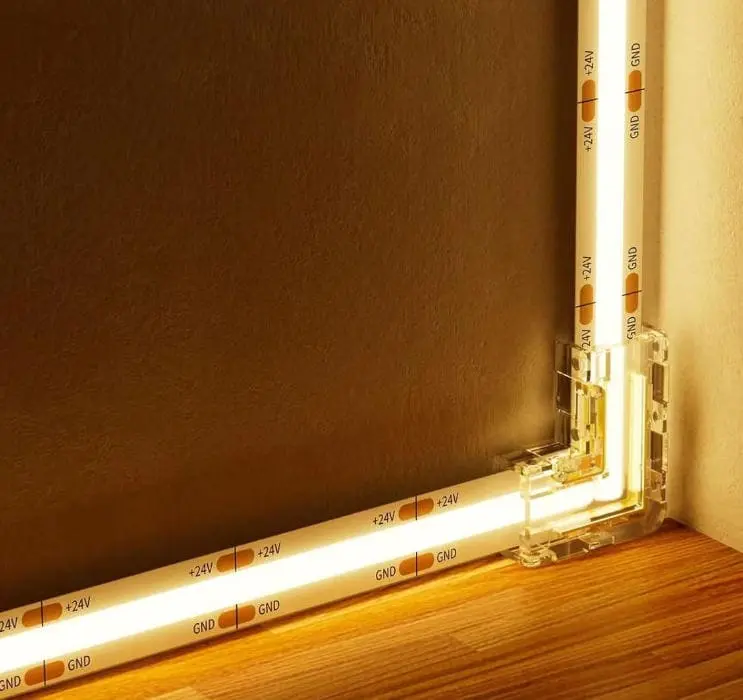
When inspecting the strip, look for the small copper ovals or lines that traverse the width of the PCB. There will usually be a small scissor icon printed nearby. You must cut exactly through the center of these copper pads.
The Soldering Challenge
While cutting is easy, reconnecting is difficult on slim strips.
- Tiny Pads: On a 3mm wide strip, the copper pads for Positive (+) and Negative (-) are microscopic. Soldering wires to these without bridging them (creating a short circuit) requires a steady hand and a fine-tip soldering iron.
- Connector Limitations: Most "solderless connectors" (plastic clips) found on Amazon are designed for 8mm or 10mm strips. It is very difficult to find reliable clip-on connectors for 3mm or 4mm strips that fit inside a slim profile. The connectors are often wider than the strip itself.
Factory Customization is Best
For projects requiring high precision, we advise clients to order "custom tails." This means you provide the manufacturer with a schedule of lengths (e.g., "15 pieces at 650mm with 1m wire leads"). We cut the strips at the factory and machine-solder the leads. This guarantees a strong connection and eliminates the risk of short circuits on site. It also speeds up installation significantly, as your electricians just need to stick the lights down and connect the driver.
Quick Guide to Cutting Slim Strips
| Step | Action | Precaution |
|---|---|---|
| 1. Measure | Measure the channel, deduct 10mm for wire clearance. | Do not measure the full shelf width; account for the wire exit. |
| 2. Locate Cut Line | Find the copper pads with the scissor mark. | Never cut between pads; this will kill the section. |
| 3. Cut | Use sharp electrician's scissors. | Cut straight. A diagonal cut reduces soldering area. |
| 4. Test | Power up the strip immediately after cutting. | Verify it works before pasting it into the profile. |
Conclusion
Choosing the right slim COB LED strip 8 requires balancing three key factors: internal profile dimensions, thermal management, and voltage selection. By measuring the clear internal width and adhering to safe power limits, you ensure a durable, seamless installation. For the best results in complex joinery, rely on factory-customized lengths to avoid difficult soldering work.
Footnotes
- Provides a comprehensive definition of Printed Circuit Boards (PCBs). ↩︎
- Explains the physical principle of thermal expansion in materials. ↩︎
- Wikipedia is an authoritative source, and the page directly explains voltage drop. ↩︎
- Authoritative source (energy.gov) with a clear explanation of color temperature (CCT) and not a PDF. ↩︎
- Explains the MacAdam ellipse and its relevance to LED color consistency. ↩︎
- Explains what thermal tape is and its use in electronic applications. ↩︎
- Wikipedia is an authoritative source, and the page directly explains heat sinks. ↩︎
- Defines Chip-on-Board (COB) technology used in LED strips. ↩︎