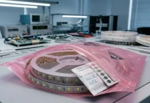
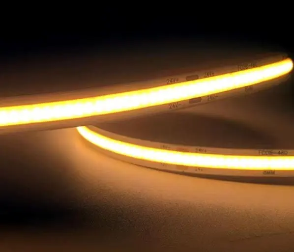
When we analyze returned products in engineering lab, we often see a common pattern: a lighting project looked perfect on day one, but six months later, the client complains about dim ends or shifting colors. This is the silent killer of large-scale installations. At our place, we know that high-density COB strips—often packing 480 chips per meter—are particularly sensitive to electrical resistance 1. If you don't catch voltage drop issues during the mockup phase, the heat generated during prolonged operation will inevitably expose them, leading to costly rework for contractors and disappointed end-users.
The most effective way to evaluate voltage drop is to measure the voltage at both the input and the tail end of the strip while it is fully operational and thermally stabilized. You must verify that the drop remains under 10% and visually inspect for brightness gradients or color temperature shifts.
Let’s break down exactly how you can diagnose, measure, and prevent this issue to ensure your projects stand the test of time.
How Do I Accurately Measure Voltage Drop in My COB LED Strips After Long-Term Use?
We frequently guide our distributor partners through troubleshooting sessions when they face unexpected dimming in the field. It is frustrating to guess whether the power supply is failing or the wire gauge 2 is too thin. In our experience, the only way to get a definitive answer is to stop guessing and start measuring with a disciplined protocol.
To accurately measure voltage drop, use a multimeter to check the voltage at the power source and the very end of the LED run while the lights are at 100% brightness. Perform this test after the strip has run for at least 30 minutes to account for heat-induced resistance increases.
The Importance of "Hot" Testing
Many installers make the mistake of testing the voltage immediately after turning the lights on. However, copper has a positive temperature coefficient. This means that as your LED strip heats up, the electrical resistance in the PCB traces increases. In our testing facility, we have observed that a strip passing a "cold" test might fail once it reaches its operating temperature of 45°C to 55°C.
To get real-world data, you must let the installation run for at least 30 to 60 minutes. This allows the copper traces and the LEDs to reach thermal equilibrium 3. Only then will your multimeter give you a reading that reflects the true operating conditions.
Step-by-Step Measurement Protocol
You do not need expensive lab equipment. A standard digital multimeter is sufficient. Here is the process we recommend to our clients:
- Set Up: Turn on the LED strip to full white (maximum power).
- Warm Up: Wait for 30 minutes.
- Measure Input (V_in): Place your probes on the solder pads where the power wire connects to the strip.
- Measure Output (V_out): Place your probes on the solder pads at the very end of the run.
- Calculate: Use the formula
(V_in - V_out) / V_in * 100.
Interpreting Your Results
Once you have your numbers, you need to know if they are acceptable. While some industry standards are loose, we hold our products to stricter limits to ensure longevity.
Table 1: Voltage Drop Acceptability Standards
| Drop Percentage | Visual Effect | Verdict | Action Required |
|---|---|---|---|
| 0% - 3% | None. Perfect uniformity. | Excellent | No action needed. Ideal for high-end retail. |
| 3% - 10% | Barely visible to the naked eye. | Acceptable | Standard for general commercial lighting. |
| 10% - 15% | Slight dimming at the end; possible warmth in color. | Caution | Consider power injection at the end. |
| > 15% | Obvious dimming; white looks yellow/orange. | Critical Failure | Must rewire. Add power injection or shorten run. |
If your calculation shows a drop greater than 10%, the LEDs at the end are being under-driven. This might seem like it extends life, but it actually causes uneven aging across the strip.
What Are the Visible Signs That My High-Density Strips Have a Voltage Drop Problem?
During site visits to inspect older installations, we often spot issues that the maintenance team missed. It is easy to ignore a slight change in light quality if you look at it every day. However, for a lighting designer or a discerning property owner, these visual cues are glaring evidence that the electrical design was not robust enough for the high-density COB strips used.
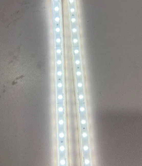
Visible signs of voltage drop include a noticeable brightness gradient where the strip becomes dimmer towards the end and a color shift where cool white light turns warmer or yellowish. These symptoms appear because the voltage at the tail is insufficient to drive the blue die in the phosphor mix.
The "Yellow Tail" Phenomenon
The most distinct sign of voltage drop in white COB LED strips is color shifting. White LEDs are actually blue LEDs covered in yellow phosphor. When the voltage drops significantly, the blue LED chip does not receive enough energy to emit light at its full intensity. However, the phosphor continues to glow.
This results in the light looking "warmer" or more yellow at the end of the run compared to the beginning. If you installed a 4000K strip, the start might measure 4000K, but the end could drop to 3000K or lower. In high-end retail or museum projects, this inconsistency is unacceptable.
Distinguishing Voltage Drop from Phosphor Aging
It is crucial to distinguish between voltage drop (an electrical issue) and phosphor aging (a chemical issue). We often see customers confuse the two.
- Voltage Drop: The dimming is linear. The start is bright, and it gradually fades to the end. If you inject power at the end, the brightness restores immediately.
- Phosphor Aging: The strip is dim or discolored in random patches or uniformly across the whole length, even if the voltage is correct. This is usually due to poor heat dissipation degrading the phosphor over time.
Visual Inspection Checklist
When evaluating a project that has been running for months, look for these specific indicators.
Table 2: Visual Symptoms and Likely Causes
| Visual Symptom | Pattern | Likely Cause | Verification Method |
|---|---|---|---|
| Linear Dimming | Bright at start, fading smoothly to the end. | Voltage Drop | Measure voltage at the tail. |
| Color Shift (Red/Yellow) | End of the strip looks warmer than the start. | Voltage Drop | Check if V_out is < 20V (for 24V strip). |
| Random Dark Spots | Specific sections are dark; others are bright. | Micro-fractures | Press on the dark section to see if it lights up. |
| Flickering | Entire strip or large sections blink. | Loose Connection | Check input terminals and solder joints. |
| Overall Low Brightness | The whole strip is dim, start to finish. | Power Supply Issue | Measure output voltage at the PSU. |
By training your eye to spot the "gradient" versus the "patch," you can quickly determine if you need to fix the wiring (voltage drop) or replace the product (thermal damage).
Does the PCB Quality Affect the Voltage Stability of My COB Strips Over Time?
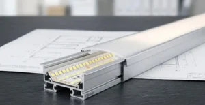
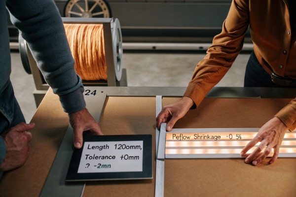
When we negotiate with our raw material suppliers, we are obsessive about copper thickness. It is the single most expensive component in the raw PCB, so many budget manufacturers try to cut costs here. However, we know that for high-density COB strips running for thousands of hours, the quality of the PCB is the foundation of electrical stability.
PCB quality is critical for voltage stability; thicker copper traces (2oz to 4oz) significantly reduce resistance and heat buildup. Thin PCBs suffer from higher resistance, which worsens over time due to thermal cycling, leading to accelerated voltage drop and potential failure.
The Role of Copper Thickness
Think of the PCB traces as a water pipe. A narrow pipe (thin copper) restricts flow and loses pressure (voltage) over distance. A wide pipe (thick copper) allows flow with minimal loss.
Standard LED strips often use 1oz (35μm) copper. This is fine for low-power strips. However, for dotless COB strips, which draw higher current to create that seamless line of light, 1oz is insufficient. We standardize on 2oz (70μm) or even 3oz for our high-power project series.
Thicker copper does two things:
- Lowers Resistance: It allows current to travel further without dropping voltage.
- Dissipates Heat: It acts as a heatsink, pulling heat away from the LED chips.
Thermal Cycling and Micro-Fractures
Over prolonged operation, LED strips heat up and cool down daily. This expansion and contraction puts stress on the PCB. If the PCB is low quality or too thin, this mechanical stress can cause micro-fractures in the copper traces.
These fractures create "choke points" where resistance spikes. You might measure the strip on day one and it is fine. But after 6 months of thermal cycling, a micro-fracture develops, resistance shoots up, and suddenly you have a massive voltage drop in the middle of a run. This is why we use double-layer PCBs with rolled annealed copper, which is more flexible and durable than standard electrolytic copper.
Table 3: PCB Specification vs. Performance Reliability
| PCB Spec | Copper Weight | Best Application | Voltage Drop Risk | Durability |
|---|---|---|---|---|
| Economy | 1oz (35μm) | Short runs (< 2m), low power. | High | Low. Prone to overheating. |
| Standard | 2oz (70μm) | Standard commercial projects (5m). | Low | Good. Industry standard for pro use. |
| Premium | 3oz - 4oz | Long runs (> 10m), high power. | Minimal | Excellent. Handles thermal stress well. |
When sourcing for a large project, always ask for the PCB specification. If a supplier cannot tell you the copper weight, it is a red flag.
solderless connectors 6
What Steps Can I Take to Minimize Voltage Drop in My Large-Scale LED Projects?
We always tell our contractor partners that physics is non-negotiable. In large-scale projects where runs exceed 10 or 20 meters, relying on a single power feed is a recipe for failure. Proper circuit planning is the difference between a professional install and one that needs constant maintenance.
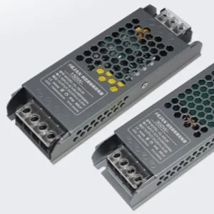
To minimize voltage drop, use 24V or 48V LED strips instead of 12V, and implement power injection at both ends or the middle of the run. Additionally, ensure you use appropriately sized gauge wires for feed lines to reduce resistance before the power even reaches the strip.
The Power of Higher Voltage
The most effective change you can make is switching from 12V to 24V (or even 48V).
- 12V Systems: High current. High voltage drop. Good for cars, bad for long architectural runs.
- 24V Systems: Half the current of 12V for the same wattage. This reduces voltage drop by 75% (since power loss is proportional to the square of the current).
For any project run longer than 5 meters, we almost exclusively recommend 24V COB strips.
digital multimeter 9
Power Injection Strategies
"Power Injection" simply means running an extra wire from the power supply to the end or middle of the LED strip. This equalizes the pressure (voltage) across the entire length.
- Single End Feed: Good for up to 5m (24V).
- Dual End Feed: Powering both the start and the end. This effectively doubles the maximum run length because the current only has to travel half the distance to the middle. Good for up to 10m.
- Middle Injection: For very long runs, you can run a thick "backbone" cable alongside the strip and tap into the strip every 5 or 10 meters.
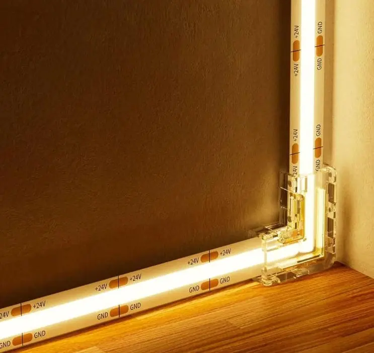
Avoid Solderless Connectors
We see many failures caused by "Hippo clips" or solderless connectors. While convenient, they have a small contact area. Over time, oxidation and thermal expansion loosen these connections, creating high resistance right at the input.
For a permanent, low-drop connection, soldering is mandatory. A direct solder joint ensures the lowest possible resistance and won't degrade over time like a mechanical clip.
Wire Gauge Selection
Don't let the voltage drop happen in the wall before it even hits the light. If your power supply is 10 meters away from the start of the strip, using a thin 20AWG wire will cause significant loss. Use online voltage drop calculators to size your feed wires correctly (often 14AWG or 16AWG is needed for long lead wires).
Conclusion
Evaluating voltage drop in high-density COB strips requires looking beyond the initial installation. By measuring voltage under "hot" operating conditions, recognizing the visual signs of color shift, and prioritizing high-quality PCBs with thick copper, you can ensure your lighting effects remain consistent for years. Always plan your power distribution with 24V systems and proper injection points to mitigate resistance issues before they become visible problems.
positive temperature coefficient 10
Footnotes
- Provides fundamental background on the physical property causing voltage drop in conductors. ↩︎
- Industry standard for the sizing and specifications of electrical conductors. ↩︎
- Industry standard terminology for stable operating temperature in electronic components. ↩︎
- Major manufacturer documentation on connector types and their reliability in electrical systems. ↩︎
- Explains the technology and components used in white light emission for LEDs. ↩︎
- Technical documentation from a leading manufacturer on the primary measurement tool used. ↩︎
- Official metrology source explaining how temperature affects electrical properties and resistance. ↩︎