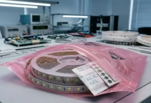
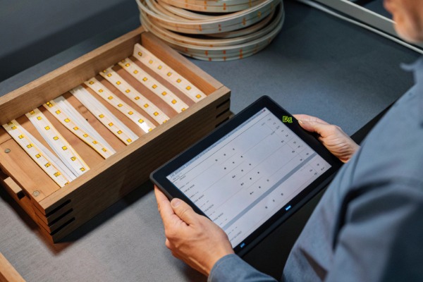
When we calibrate production lines for a new batch of high-density COB strips, the most critical parameter we verify is the circuit repeatability 1. We often see project managers struggle because they assumed a standard cutting length, only to find the strip didn't fit their aluminum profile without leaving a dark spot. The frustration of having to modify joinery on-site because the lighting product didn't match the drawings is a pain we actively try to prevent during the initial consultation phase.
To inquire effectively, you must explicitly ask for the precise measurement in millimeters between cut marks (e.g., 25mm, 50mm) rather than accepting general estimates. You should also confirm how the operating voltage and LED density influence this interval, and request a technical datasheet to validate that the physical cut points align with your specific architectural constraints.
Understanding the nuances of cutting units is essential for a seamless installation. Let's break down exactly what you need to know and ask.
What is the standard cutting interval for high-density COB strips to ensure precise fitting?
In our engineering department, we constantly balance the trade-off between high voltage and short cutting segments. We know that for a distributor, the "standard" can be a moving target depending on the specific chip architecture used in that month's production run.
The standard cutting interval for high-density COB strips typically ranges from 25mm to 50mm for 24V models, while 12V options may offer shorter segments around 10mm to 25mm. However, this varies significantly based on the circuit design and LED density, so you must verify the exact millimeter pitch to ensure precise fitting in rigid profiles.
The Relationship Between Voltage and Cut Lengths
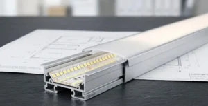
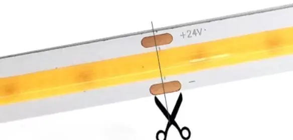
When we design a circuit for a 24V LED strip 2, we are essentially grouping LEDs in series to handle that voltage. A higher voltage generally requires more LEDs in a single "group" or series string. The cutting point is located between these groups. Therefore, a 24V strip will naturally have a longer cutting unit than a 12V strip.
For high-density COB strips (Chip on Board 3), where the diodes are packed directly onto the PCB, this relationship is crucial. Many of our clients assume that "high density" automatically means "short cut length." While often true, it is not a guarantee. A 24V COB strip with 480 LEDs/m might still have a cutting length of 50mm if the circuit topology is designed for maximum run length rather than precision cutting.
Why "Standard" Varies by Manufacturer
There is no global ISO standard that dictates a 24V COB strip must be cut every 50mm. It depends entirely on the PCB layout.
- Circuit Efficiency: Some factories design for longer segments to reduce the number of resistors or current control ICs, which lowers heat and cost.
- LED Density: A strip with 320 LEDs/m will have a different physical spacing than one with 512 LEDs/m. Since the cut point must fall between specific chips, the density dictates the math.
Critical Inquiry Checklist
When you are emailing a supplier, do not just ask "What is the cut length?" Use this table to guide your technical inquiry to ensure you get the data you need for your lighting design.
| Specification | Typical Value (24V) | Typical Value (12V) | Why You Must Ask |
|---|---|---|---|
| Cut Unit Length | 25mm - 50mm | 10mm - 25mm | Determines if the strip fits your specific joinery or shelf width. |
| LED Density | 320 - 512+ LEDs/m | 320 - 512+ LEDs/m | Higher density usually allows for shorter cuts, but verify the math. |
| Solder Pad Size | 2mm - 4mm width | 2mm - 4mm width | High density often means smaller pads, making soldering difficult. |
| Dark Zone Radius | < 1mm | < 1mm | Ensures the light reaches the very end of the cut segment. |
The "Dark Zone" Risk
One issue we frequently highlight to designers is the "dark zone" at the cut point. In standard SMD strips, there is a clear gap between LEDs. In COB strips, the light is continuous. However, at the cut point, there is a necessary gap in the phosphor coating 4 to expose the copper pads. If this gap is too wide, or if the circuit design places the last LED too far from the cut line, you will see a visible shadow when two strips are butted together. Always ask for a close-up photo of the illuminated cut point.
Does a shorter cutting unit help reduce waste during complex cabinet installations?
We have observed countless installation sites where piles of "off-cut" scraps accumulate in the trash—money literally thrown away. When we consult with large-scale contractors, we emphasize that the cutting unit is not just a technical spec; it is a cost-saving metric.
A shorter cutting unit significantly reduces waste during complex installations by allowing the strip to be trimmed closer to the required length, minimizing unusable off-cuts. This precision is particularly vital for cabinetry and joinery where dimensions are fixed, ensuring that the lighting fills the entire channel without leaving dark gaps or requiring excessive trimming.
The Mathematics of Waste
Imagine you are lighting a series of kitchen cabinets. Each cabinet internal width is exactly 580mm.
- Scenario A (50mm Cut Unit): You can cut the strip at 550mm or 600mm. You must choose 550mm to fit inside. This leaves a 30mm unlit gap (15mm on each side). Or, if you cut a fresh piece, you might waste nearly 49mm if the run was just slightly over a cut point.
- Scenario B (10mm Cut Unit): You can cut the strip at 580mm exactly (or 570mm/580mm depending on the start). You fill the space perfectly.
Over a single cabinet, the waste is negligible. But in a hotel project with 500 rooms and custom millwork, a long cutting unit can result in 5% to 10% more material usage just to accommodate the "nearest cut point."
Precision in Joinery and Recessed Profiles
For high-end architectural projects, the tolerance for dark edges is zero. Designers want the "bar of light" effect.
- The Shadow Problem: If your profile is 1000mm and your strip cut length is 62.5mm (a common oddity in some imperial-converted designs), 16 units = 1000mm exactly. Perfect. But if the profile is 1010mm? You have a 10mm dark gap.
- Shorter Units = Better Fill: A 12.5mm or 25mm cut unit allows the installer to fill that 1010mm profile up to 1000mm or 1012.5mm (if the end cap allows), drastically reducing the visual shadow.
Cost Implications vs. Product Cost
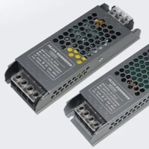
There is an opposing viewpoint to consider. Strips with shorter cutting units (often higher density or 12V) might be slightly more expensive per meter due to the manufacturing complexity 5 or the need for more copper to handle the current in 12V systems.
However, you must calculate the Total Installed Cost:
- Material Cost: Price per meter.
- Waste Factor: Percentage of strip discarded.
- Labor: Time spent trying to hide dark corners or center a too-short strip.
Inquiry Strategy for Waste Reduction
When speaking to us or any supplier, present your project scope.
- "We have 2000 meters of shelving with variable lengths. Do you have a high-density option with a cut unit under 25mm?"
- "Can you provide a waste simulation if we use your 50mm cut standard versus a 25mm custom option?"
We often advise clients that for straight, long cove lighting runs (e.g., 10 meters around a ceiling), the cut unit matters less. But for "furniture integrated lighting," the shorter the unit, the better the ROI.
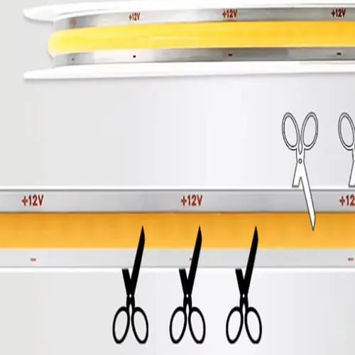
How clearly are the cut marks labeled on the PCB for on-site adjustments?
During our quality control inspections, we pay close attention to the silk-screen printing on the PCB. We know that a tired electrician working in a dimly lit room needs to see exactly where to cut, or they risk destroying a section of the strip.
Cut marks on COB strips must be clearly labeled with visible scissors icons or black lines printed directly on the PCB, distinguishable through the phosphor gel. You should inquire if the copper solder pads are visually distinct from the continuous coating, as ambiguous markings often lead to cutting through active circuits and voiding warranties.
The Challenge of COB Phosphor Coating
The defining feature of COB (Chip on Board) is the continuous layer of yellow phosphor silicone 6 that covers the LEDs. This creates the dotless effect, but it also obscures the circuit board underneath. Unlike SMD strips where the copper pads are exposed and obvious, COB strips are "encapsulated."
If the manufacturer does not print a strong, contrasting mark on top of the PCB before the gel is applied (or on the back), the installer is flying blind. They might guess where the cut point is based on the solder pads, but if the pads are covered by gel, they might cut into the circuit.
Types of Indicators
We utilize different methods to mark cut points, and you should ask which one is used:
- Black Line across the Phosphor: Some advanced manufacturing processes allow for a mark on top of the gel, though this is rare.
- PCB Silk Screen (Visible through Gel): The most common method. A black line or scissor icon is printed on the white PCB. The yellow gel is translucent enough to see it. Critical Question: Is the ink dark enough to see through the specific thickness of the phosphor used?
- Back-side Marking: Marks are printed on the adhesive tape side (3M tape). This is helpful, but annoying for installers who have already adhered the strip and need to trim the end.
- Exposed Copper Pads: The best method for clarity. The phosphor gel stops right before the cut point, leaving the copper pads exposed. This serves two purposes: easy soldering and a clear visual stop/start point.
Solder Pad Clearance and Safety
A major issue with unclear markings is the risk of "shorting." If a cut is made slightly off-center because the line was blurry, the copper traces might touch the aluminum profile or bridge positive and negative layers.
Inquiry Template for Markings
When evaluating a sample or asking a supplier, use these specific questions:
- "Are the cut lines printed on the front or the back of the PCB?"
- "Is the phosphor layer continuous over the cut point, or is there a gap exposing the solder pads?"
- "Can you send a photo of the cut point under normal lighting conditions?"
Visualizing the Difference
| Feature | Poor Quality Indicator | High Quality Indicator |
|---|---|---|
| Visibility | Faint gray line, hard to see under yellow gel. | Sharp black line or "Scissors" icon. |
| Solder Pads | Fully covered by silicone/gel. | Exposed or thinly covered for easy access. |
| Precision | Mark is roughly placed near the pads. | Mark is exactly centered between pads. |
| Back Marking | None. | Repeated measurement markings on the liner. |
If your installers complain about "guessing" where to cut, you are buying from the wrong batch. Clear labeling is a hallmark of a manufacturer who understands the on-site reality.
Can I request custom cutting lengths from the factory to speed up my project installation?
When we receive inquiries for large-scale commercial projects, we often suggest customization as a solution to labor costs. We understand that while off-the-shelf products are convenient, they are rarely the most efficient solution for a project requiring thousands of identical fixtures.
Yes, you can request custom cutting lengths from the factory, provided your order volume meets the Minimum Order Quantity (MOQ) for a custom PCB run. This customization allows you to align the circuit design perfectly with your project's dimensions, significantly speeding up installation by eliminating manual measuring and trimming on-site.

The Economics of Customization
Customizing the cutting length isn't just about taking a pair of scissors to the reel before shipping. It often involves redesigning the PCB circuit.
- If you need a 33mm cut length because your fixtures are 330mm long, we cannot simply cut a standard 50mm strip. We must alter the resistor values and LED grouping to create a circuit that repeats every 33mm.
- NRE (Non-Recurring Engineering) Costs: There is usually a setup fee for the new PCB mold and stencil.
- MOQ: We typically require 500m to 1000m for a custom circuit layout to justify the production setup.
Pre-Cut Service vs. Custom Circuit
There is a distinction you must understand when asking for "custom lengths":
Service: Pre-Cutting Standard Strips
- What it is: You buy a standard 50mm-cut strip, and we cut it into 1-meter segments for you at the factory.
- Benefit: Saves labor on site. Soldering leads can be done by machine at our factory.
- Constraint: The length must still be a multiple of the standard cut unit (e.g., 50mm, 100mm, 150mm). You cannot get 1025mm if the unit is 50mm.
Product: Custom Circuit Design
- What it is: We change the copper layout to create a new cut unit (e.g., 28mm).
- Benefit: Perfect fit for unique architectural elements.
- Constraint: Higher MOQ and longer lead time (3-4 weeks for prototype).
When to Choose Customization
We recommend custom cutting lengths in the following scenarios:
- OEM Manufacturing: You are building a specific lamp or light fixture.
- Large Retail Rollouts: You are lighting 500 stores with identical shelf sizes.
- Complex Curves: You need an ultra-short cut length (e.g., 10mm) to navigate tight radii without lifting.
How to Inquire About Customization
To get a serious response from a supplier regarding customization, provide data immediately:
- Target Cut Length: "We need a cut unit of roughly 30mm."
- Total Project Volume: "This is for a 2000m initial order."
- Voltage Requirement: "Must remain 24V."
- Application: "Installed in 305mm wide display cases."
Customization Trade-offs
| Factor | Standard Strip | Custom Cut Length Strip |
|---|---|---|
| Lead Time | In stock / 3-5 days | 15-25 days (production) |
| Cost | Standard market price | Setup fee + Potential unit premium |
| Flexibility | Good for general use | Limited to specific project dimensions |
| Installation Speed | Slow (measure, cut, solder on site) | Fast (plug and play if pre-cut) |
By leveraging factory customization, you shift the burden of precision from the construction site to our controlled manufacturing environment. This reduces risk and speeds up project completion.
How do specific connector types interact with the cutting points of COB strips?
We frequently field calls from panicked installers who have bought "solderless connectors" that don't work with their high-density strips. We know that the physical interface 7 between the strip and the power source is the most common point of failure in any lighting system.
Specific connector types, such as "hippoclips" or slide-in terminals, often fail with COB strips because the continuous phosphor layer interferes with the contact pins. You must ask if the cutting points have sufficient clearance and exposed copper to accommodate these connectors, or if the phosphor coating requires manual peeling before connection.
The "Phosphor Barrier"
Standard SMD strips have flat, exposed copper pads. You slide a connector on, crimp it, and the metal teeth bite into the copper.
COB strips are different. The yellow phosphor gel often runs right up to, or even slightly over, the cut line.
- Interference: Standard connectors cannot pierce the gel effectively. Even if they do, the connection is weak and prone to arcing.
- Thickness: The gel adds height. A connector designed for a 0.3mm PCB might not close over a COB strip that is 1.5mm thick due to the gel.
Connector Compatibility Inquiry
When inquiring about cut units, you must simultaneously ask about connection methods. A 25mm cut unit is useless if the solder pad is so small and covered in gel that you can't attach a wire to it.
Key Questions to Ask:
- "Is the solder pad 'clean'?" Ask if the manufacturing process leaves the copper pad bare, or if you have to scrape the gel off. Scraping gel on-site is time-consuming and risks damaging the PCB.
- "What is the pad width?" High-density strips often squeeze the pads to fit more LEDs. A standard 10mm connector might need 4mm wide pads, but the strip might only have 2.5mm pads.
- "Do you recommend specific connectors?" We often stock connectors specifically designed to pierce our specific brand of COB coating. Buying generic connectors from Amazon is a gamble.
Solder vs. Solderless
We always recommend soldering for long-term reliability, especially for B2B projects. However, we know labor shortages make solderless connectors attractive.
unclear markings 8
- If using Solderless: You need a "piercing" type connector specifically for COB, not a "surface contact" type.
- If Soldering: The cut unit area must have enough thermal mass. If the cut unit is too short (e.g., 10mm), the heat from the soldering iron might travel to the nearby LED chip and damage it, causing immediate failure.
Hardness of the Encapsulation
Another technical nuance is the hardness of the silicone or epoxy used.
- Soft Silicone: Easy to peel back with a fingernail or knife to expose copper.
- Hard Epoxy: Very difficult to remove without scratching the copper trace underneath.
- Inquiry: "What is the durometer (hardness) of the encapsulation? Is it peelable for soldering?"
Connector Compatibility Matrix
| Connector Type | COB Compatibility | Main Issue | Solution |
|---|---|---|---|
| Slide-in (Surface) | Low | Gel blocks contact. | Peel gel manually (slow). |
| Piercing (Teeth) | Medium/High | May not penetrate hard gel. | Use specific COB-rated connectors. |
| Soldering | High | Heat management. | Skilled labor required. |
| Factory Molded | Perfect | None. | Order pre-soldered tails from factory. |
By addressing the connector issue during the inquiry about cutting lengths, you ensure that the strip isn't just the right length, but that it can actually be powered up reliably.
3M tape 9
Conclusion
Inquiring about the cutting unit length of high-density COB LED strips goes beyond simply asking for a number. It requires understanding the interplay between voltage, density, and installation constraints. By asking specific questions about millimeter precision, waste reduction, label visibility, and connector compatibility, you protect your project from costly on-site modifications. As a manufacturer, we appreciate buyers who ask these detailed questions—it signals a professional partnership where we can deliver the exact precision your project demands.
ISO standard 10
Footnotes
- NIST provides standards for measurement precision and repeatability in manufacturing and engineering. ↩︎
- Technical guidance from a leading power supply manufacturer on constant voltage LED systems. ↩︎
- Provides a foundational definition of the COB technology discussed throughout the article. ↩︎
- Explains the chemical properties of phosphors used to convert LED light. ↩︎
- News context on electronics manufacturing and global supply factors affecting production costs. ↩︎
- Research from the Lighting Research Center on LED encapsulation and phosphor materials. ↩︎
- IPC standards for electronic interconnects and connection reliability in lighting systems. ↩︎
- OSHA guidelines regarding electrical hazards and circuit protection in industrial settings. ↩︎
- Official documentation for the adhesive backing commonly used on LED strips. ↩︎
- Reference to ISO standards for printed circuit boards and electronic assembly quality. ↩︎