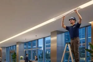
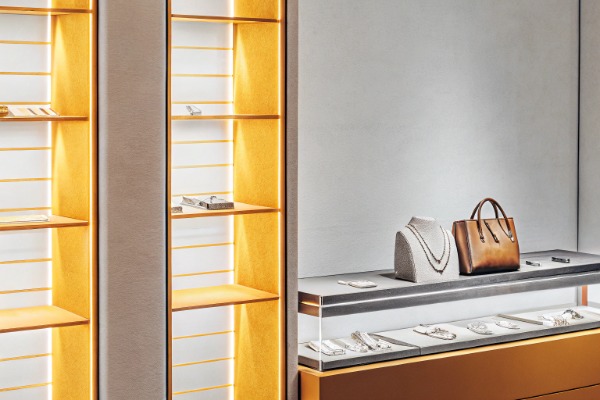
We often see clients frustrated by samples that look perfect on a desk but fail miserably when installed in a ceiling cove. Nothing ruins a high-end architectural project faster than seeing individual beads of light reflected on a polished marble floor. Before you commit to a bulk order for your next commercial project, you need a rigorous verification process that mimics real-world conditions, not just a supplier's optimized demo video.
To verify a "dotless" claim, request a sample installation using your specific aluminum profile and diffuser height rather than relying on bare-strip demos. Inspect the light output at low dimming levels, view it from side angles, and check reflections on glossy surfaces, as these conditions frequently reveal hidden hotspots.
Let's break down the technical specifics so you can audit your supplier's claims effectively and ensure the final result matches the design intent 1.
What is the minimum chip density required to guarantee a seamless light line without spotting?
When we engineer our project-grade strips, we constantly balance power consumption 2 with LED density. Many buyers assume any "high density" strip will work, but that is a costly misconception. If the pitch between chips doesn't match your channel depth, you will end up with a "zipper" effect that no amount of diffusion can fix.
For standard aluminum profiles with a milky diffuser, a minimum density of 120 LEDs per meter is generally required to achieve a seamless effect. However, for shallow surface-mounted channels, you must use at least 240 LEDs per meter or switch to COB (Chip-on-Board) technology to eliminate visible spotting completely.
The Relationship Between Pitch and Distance
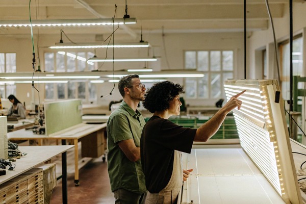
The "dotless" effect is not magic; it is simple physics. It relies on the relationship between the distance between individual LED chips (pitch) and the distance from the chips to the diffuser cover. In our production line, we refer to this as the "diffusion triangle." If the light from two adjacent LEDs does not overlap before it hits the cover, you will see a dark spot.
To guarantee a seamless line of light, you generally need a higher density of LEDs as the profile gets shallower. Standard SMD (Surface Mounted Device) strips, such as the 2835 or 5050 series 3, have physical gaps between the diodes.
- Standard Density (60 LEDs/m): The chips are spaced about 16mm apart. This almost always requires a very deep profile (over 20mm) to hide the dots.
- High Density (120 LEDs/m): The chips are spaced about 8mm apart. This is the industry standard for "dotless" in profiles that are at least 15mm deep.
- Ultra-High Density (240+ LEDs/m): The chips are very close, allowing for shallower profiles.
Why COB Technology is the Safer Bet
If your project requires extremely shallow profiles—for example, under-cabinet lighting or joinery details—standard SMD strips often fail to provide a dotless effect. This is where we recommend COB (Chip on Board) technology.
Unlike traditional strips where individual diodes are soldered onto the PCB, COB strips feature a continuous layer of phosphor over the chips. This creates a solid line of light directly at the source. Even in a profile with a depth of only 5mm, a COB strip will appear completely uniform.
Density Recommendations by Application
Below is a guide we use internally to recommend densities based on the installation environment.
| Application Scenario | Profile Depth | Recommended Technology | Minimum Density |
|---|---|---|---|
| Deep Ceiling Coves | > 20mm | Standard SMD | 60 - 120 LEDs/m |
| Standard Surface Mount | 10mm - 15mm | High Density SMD | 120 - 180 LEDs/m |
| Shallow Joinery / Shelves | < 10mm | Ultra High SMD or COB | 240+ LEDs/m (or COB) |
| Direct View (No Profile) | N/A | COB / Neon Flex | COB 320+ LEDs/m |
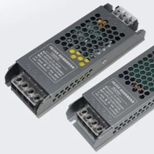
Critical Thinking: The Voltage Drop Trap
While increasing density solves the spotting issue, it introduces a new problem: voltage drop. A strip with 240 LEDs/m draws significantly more power. If you are running long lengths (over 5 meters), the voltage may drop at the tail end. This causes the LEDs to dim, and when they dim, the "dotless" saturation can fail, revealing the internal structure of the strip. Always verify that the PCB (Printed Circuit Board) is thick enough (usually 3oz or 4oz copper) to handle the current of high-density strips.
Do I need deep aluminum profiles to achieve a true dotless effect with these strips?
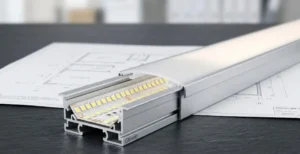
In our experience supplying contractors in Australia and Germany 4, the aluminum profile is often the overlooked variable in the lighting equation. You might have the best LED strip on the market, but placing it in a profile that is too shallow is a recipe for visual failure. We always advise testing the strip and profile combination together.
Deep aluminum profiles are not strictly necessary if you utilize COB technology or extremely high-density strips (over 240 LEDs/m). However, for standard SMD strips, a profile depth of at least 15mm is crucial to allow light to overlap and blend before hitting the diffuser, ensuring a smooth, continuous glow.

The Physics of Light Diffusion
The depth of the aluminum profile acts as a mixing chamber for the light. The deeper the profile, the further the light travels before it hits the plastic cover. This distance allows the beam angle of each individual LED (usually 120 degrees) to widen and overlap with its neighbor.
When we consult with lighting designers, we often explain that depth buys you forgiveness. If you use a deep profile (e.g., 20mm or more), you can often get away with using a cheaper, lower-density LED strip (like 60 or 120 LEDs/m) and still achieve a dotless look. This can save money on the project budget. However, if the design calls for a sleek, low-profile fixture, you lose that "mixing distance" and must spend more on high-density or COB strips to compensate.
Space Constraints vs. Visual Performance
In many renovation projects, you do not have the luxury of deep recesses. Carpenters and joiners often leave only shallow grooves for lighting. In these cases, relying on profile depth is impossible.
If you are forced to use a shallow profile (e.g., 7mm height), you must change your strategy. You cannot rely on the profile to diffuse the light 5. Instead, the "dotless" characteristic must come from the strip itself (using COB) or a specialized heavy-diffusion cover.
Profile Selection Guide
When selecting a profile, consider the "clearance height"—the internal distance from the PCB mounting surface to the diffuser.
Impact of Profile Shape on Diffusion
It is not just about depth; the shape matters too.
- Square/U-Channel: Standard diffusion. Light goes straight up.
- Corner/V-Channel: These often have more depth relative to the mounting surface because of the 45-degree angle, providing better diffusion than a flat channel of the same size.
- Recessed Flangeless: These look great but often have tight internal dimensions. Ensure the internal width accommodates the strip without pinching, which can cause the strip to lift and create hotspots.
Cost vs. Benefit Analysis
Here is how we help clients decide between deep profiles and high-density strips.
| Strategy | Component Cost | Installation Ease | Best For |
|---|---|---|---|
| Deep Profile + Low Density Strip | Low (Strip is cheap) | Moderate (Requires deeper groove) | General ambient lighting, coves |
| Shallow Profile + COB Strip | High (COB is premium) | High (Fits anywhere) | Cabinetry, shelves, retrofits |
| Standard Profile + High Density | Moderate | High | Standard commercial lighting |
The "Sagging" Risk in Deep Profiles
One hidden risk with wider, deeper profiles is the diffuser sagging. If the profile is wide (e.g., 50mm) and the plastic cover is thin, gravity or thermal expansion can cause the cover to bow inward. If the cover sags closer to the LEDs, you lose the depth you paid for, and dots may suddenly appear in the center of the fixture. Always check that the diffuser is rigid enough for the profile width.
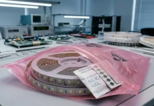
How can I test the light diffusion uniformity using a sample kit before bulk ordering?
Sending out sample kits is a daily routine for our sales team, but we notice very few clients test them rigorously. Simply plugging it in on a desk tells you nothing about how it performs in a cove or under a cabinet. To avoid surprises later, you need to stress-test the sample against the specific constraints of your project site.
You should build a realistic mock-up by mounting the sample strip inside your intended channel and viewing it from a distance of one meter. Crucially, test the strip against glossy surfaces like polished tile and dim it to 10% brightness, as these scenarios often expose uneven diffusion hidden at full power.
The "Glossy Surface" Reflection Test
This is the number one failure point we see in high-end hotels and retail stores. You might look directly at the fixture and see a perfect, dotless line of light. However, if that fixture is installed above a polished granite countertop, a glass window, or a glossy tiled floor, the surface acts as a mirror.
Mirrors do not reflect the diffused light; they reflect the source. You will see a perfect reflection of every single LED chip on the floor or counter.
- How to test: Place your sample strip inside its profile and hold it above a mirror or your phone screen.
- What to look for: If you see distinct dots in the reflection, your client will see them too. To fix this, you need a side-emitting strip or a much higher density COB strip that creates a solid phosphor reflection.
The Dimming Stress Test
Many suppliers show you samples running at 100% brightness. At full power, the sheer intensity of the light blooms and saturates the diffuser, hiding imperfections. The real test happens when you dim the lights.
In a restaurant or home theater, lights are often run at 10% or 20%. At these low levels, the "bloom" disappears. If the strip relies on brightness to hide the dots, the lower current will reveal the spacing between chips.
- Action: Connect the sample to a dimmer. Slowly lower the brightness from 100% down to 1%.
- Failure Mode: If the continuous line breaks into individual points of light at low brightness, the product is not truly dotless.
Viewing Angle Verification
Do not just look at the sample straight on. In a real room, people walk around. They view coves from below and joinery from the side.
- The Side View: Look at the profile from a shallow angle (e.g., 15 degrees). Sometimes, the walls of the aluminum profile cast shadows, or the LEDs are visible through the side of the diffuser if it isn't seated perfectly.
- The Joint Test: If you have two sample pieces, butt them together. The "dotless" effect often breaks at the connector or solder pad. A true dotless system must maintain uniformity even across connections.
Sample Verification Checklist
Use this checklist when you receive a sample kit from a supplier.
| Test Parameter | Procedure | Pass Criteria |
|---|---|---|
| Direct View | View from 1 meter away at eye level. | No visible pixelation or dark spots. |
| Reflection | Hold over a mirror/glossy surface. | Reflection appears as a solid bar, not dots. |
| Dimming | Dim to 10% and 1%. | Light remains continuous; no gaps appear. |
| Color Consistency | Check white balance against a white paper. | No pink/green tint; uniform color along length. |
| Heat Sag | Run for 30 mins. | Diffuser does not bow inward toward LEDs. |
The Camera Test
Finally, pull out your smartphone. Open the camera app and point it at the lit strip. Lower the exposure slider. Cameras are more sensitive to contrast than the human eye. If your camera sees dots, it means the diffusion is marginal. While the eye might not see them today, as the diffuser ages and yellows slightly, those dots may become visible to the naked eye later.
Does the color of the silicone cover impact the visible dotting in the final installation?
During our R&D phase for waterproof neon flex products, we spent months testing different silicone mixtures. Many buyers focus solely on the LED chip, ignoring the fact that the cover's transmission rate and opacity play a massive role in the final look. A cover that is too clear will never be dotless, no matter how dense your LEDs are.
voltage drop 6
Yes, the cover color is a critical factor in light diffusion. You must use "milky" or "opal" diffusers, which typically have 50-70% light transmission, to effectively blur hotspots. "Frosted" or semi-clear covers allow too much direct light to pass through, making individual diodes visible regardless of the strip's density.

The Trade-off: Opacity vs. Brightness
There is an inherent conflict in lighting design. To hide the dots, you need a cover that scatters light (high opacity). However, high opacity blocks light, reducing the total lumen output.
- Clear Cover: 90-95% Light Transmission. Zero diffusion. Dots are fully visible. Used only for indirect lighting where the fixture is hidden.
- Frosted / Semi-Clear: 80-85% Light Transmission. Blurs the light slightly but does not hide dots. Good for high-efficiency needs where the fixture is high up.
- Milky / Opal: 50-70% Light Transmission. This is the industry standard for "dotless." The material (usually Polycarbonate or Silicone) contains white diffusing particles that scatter photons in all directions.
Why "Frosted" is Not "Opal"
We often see purchase orders requesting "Frosted" covers when the client actually wants "Opal." In the manufacturing world, "frosted" usually means a clear material with a sandblasted texture. This texture breaks up the glare but does not mix the light enough to merge the LED points. "Opal" or "Milky" means the material itself is white all the way through.
If you use a frosted cover with a standard LED strip, you will see a "pixelated" effect. For a true solid neon look, you must specify Opal/Milky diffusers.
Kelvin shift 8
Color Shift Issues
One side effect of using thick, milky diffusers is Kelvin shift. A dense white cover can warm up the color temperature of the light.
- The Shift: A 4000K LED strip might look like 3800K or 3700K once the cover is on.
- The Solution: If your project requires a precise color temperature (e.g., matching other fixtures), ask us to bin the LEDs slightly cooler (e.g., 4200K) so that the final output through the cover hits your target of 4000K.
Material Aging and Yellowing
Not all covers stay the same color. Cheap PVC covers will yellow within a year due to UV exposure and heat from the LEDs. When the cover yellows, two things happen:
- The light becomes blue/green or muddy yellow.
- The transmission drops, and the diffusion properties change, often making dots more visible over time.
We always recommend Silicone or PMMA (Acrylic) 9 covers for long-term projects. They resist yellowing and maintain their "dotless" diffusion properties for years.
Diffuser Selection Matrix
Here is how to choose the right cover based on your priority.
| Priority | Recommended Cover | Transmission | Dotless Effect? |
|---|---|---|---|
| Maximum Brightness | Clear / Transparent | ~95% | No (Dots visible) |
| Efficiency + Glare Control | Frosted / Etched | ~85% | Partial (Pixelated) |
| Perfect Uniformity | Opal / Milky | ~60% | Yes (Seamless) |
| Black Aesthetic | Black Diffuser | ~20-30% | Yes (Dim output) |
Conclusion
Verifying a "dotless" LED installation requires more than just believing a datasheet. It demands a hands-on approach: testing samples in the actual profiles, checking performance at low dimming levels, and inspecting reflections on glossy surfaces. By understanding the interplay between chip density, profile depth, and diffuser opacity, you can ensure your lighting projects deliver the seamless, high-end aesthetic your clients expect.
aluminum profile 10
Footnotes
- The Illuminating Engineering Society sets global standards for lighting design and performance. ↩︎
- Official US government guidance on LED energy efficiency and power usage. ↩︎
- Technical specifications for industry-standard SMD LED chips from a major manufacturer. ↩︎
- Australian government lighting regulations and energy rating standards. ↩︎
- Research from the Lighting Research Center on LED light distribution and diffusion. ↩︎
- Technical explanation of electrical voltage drop in conductors. ↩︎
- General background on the physics and operation of LED technology. ↩︎
- Academic research on color temperature shifts in LEDs caused by encapsulation materials. ↩︎
- Technical documentation on the optical and aging properties of PMMA from a leading producer. ↩︎
- ISO standards for the manufacturing and tolerances of extruded aluminum profiles. ↩︎