Flying to China to inspect a factory is a significant investment, but it is the only way we can truly guarantee that a production line meets the high standards required for project-grade lighting.
To ensure product quality during an on-site inspection, you must audit the precision of the die bonding machines, the temperature profiles of the reflow soldering ovens, the uniformity of the phosphor dispensing process, and the integrity of the final aging test protocols.
Let’s break down the specific checkpoints you need to visit on the factory floor to avoid costly defects later.
How do I evaluate the precision of die bonding and phosphor coating to ensure light uniformity?
When we develop new COB products, our engineers spend hours monitoring the die bonding stage because even a microscopic misalignment here results in visible dark spots or color shifts in the final strip.
You must inspect the automated die bonders for placement accuracy within ±10µm and verify that the phosphor dispensing machines use a de-aeration process to remove micro-bubbles, ensuring a consistent coating thickness that guarantees uniform color temperature across the entire reel.

The heart of any Chip-on-Board (COB) LED strip is the placement of the flip-chips. Chip-on-Board (COB) 1 Unlike traditional SMD strips where packaged LEDs are soldered onto a board, COB technology involves mounting raw LED chips directly onto the Flexible Printed Circuit Board (FPCB). This requires extremely high precision.
Auditing the Die Bonding Station
When you walk up to the die bonding machines, check the speed and the error rate logs. These machines place hundreds of chips per meter—often up to 840 chips depending on the model. You want to see fully automated, high-speed bonders. If you see manual intervention here, it is a major red flag.
Ask the operator to show you the "reject bin." A high-quality line will automatically discard any section where a chip is misaligned. If the alignment is off, the electrical connection will be weak, leading to dead sections after a few months of use.
The Art of Phosphor Dispensing
The yellow layer you see on a COB strip is a mix of phosphor and silicone. phosphor and silicone 2 This layer determines the light uniformity and color accuracy. During your tour, look for the mixing chamber. The mixture must be vacuum-degassed before application. If air bubbles remain in the glue, they create hot spots that degrade the chip faster.
You should also check the dispensing nozzle. It must apply a perfectly even layer. If the layer is too thick in some spots and thin in others, you will see a "snake" effect where the color temperature shifts from pink to green along the strip.
Key Inspection Metrics for Die Bonding
| Inspection Point | What to Look For | Potential Risk if Ignored |
|---|---|---|
| Chip Alignment | Placement accuracy < ±10µm | Electrical shorts or open circuits. |
| Glue De-aeration | Vacuum chamber usage | Bubbles causing overheating and early failure. |
| Dispensing Speed | Constant, smooth flow | Uneven thickness leading to color banding. |
| Curing Oven | Controlled temperature ramp | Cracks in the silicone layer during bending. |
What specific soldering and PCB assembly checkpoints should I audit to prevent connection failures?
In our experience troubleshooting failed projects, the most common culprit for flickering lights is not the LED chip itself, but a cracked solder joint caused by poor PCB assembly or inadequate soldering profiles.
You should verify that the factory uses Rolled Annealed (RA) copper PCBs for flexibility, audit the reflow oven’s multi-zone temperature settings to prevent thermal shock, and confirm that Automated Optical Inspection (AOI) is used to detect cold solder joints.

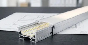
The mechanical durability of a COB strip relies entirely on the quality of the soldering and the FPCB (Flexible Printed Circuit Board). Since COB strips are often bent around corners or installed in tight aluminum profiles, the connections must be robust.
The Importance of Reflow Profiles
Soldering isn't just about getting it hot; it is about the curve. Stand in front of the reflow oven and look at the monitor displaying the temperature profile. A proper profile for lead-free solder has distinct zones: pre-heat, soak, reflow, and cooling.
If the temperature rises too fast, the flux splatters, creating solder balls that can short the tiny flip-chips. If it cools too fast, the joints become brittle. We always ask the production manager to print out the latest thermal profile graph for the current batch. If they cannot produce it, they are likely guessing the settings.
PCB Material: RA vs. ED Copper
You cannot visually tell the difference between Rolled Annealed (RA) and Electrolytic (ED) copper easily, but you can feel it. Ask for a sample of the bare PCB. RA copper is critical for high-quality strips because it allows for repeated bending RA copper 3 without cracking the copper traces. ED copper is cheaper but brittle.
Automated Optical Inspection (AOI)
After the reflow oven, there must be a machine that looks like it is taking photos of the strip. This is the AOI station. AOI station 4 It uses cameras to scan every single solder joint. Human eyes cannot reliably inspect 840 chips per meter. The AOI machine flags cold joints, tombstones (where a chip stands up), or missing solder. Ensure this machine is active and not just for show.
Comparison of PCB Copper Types
| Feature | Rolled Annealed (RA) Copper | Electrolytic (ED) Copper |
|---|---|---|
| Structure | Elongated grain structure | Vertical grain structure |
| Flexibility | High (Good for bending) | Low (Prone to cracking) |
| Application | Professional/Project Grade | Budget/Static Installation |
| Cost | Higher | Lower |
How can I verify the color binning process to guarantee consistency across my future batches?
We know that nothing frustrates a lighting designer more than receiving a second order of "3000K" strips that look visibly pinker or greener than the first batch installed in the same hallway.
Request to see the factory's ERP system for tracking bin codes, ensure they use a 3-step MacAdam ellipse standard for your orders MacAdam ellipse 5, and inspect the integrating sphere reports to confirm that Color Rendering Index (CRI) and chromaticity coordinates meet your specs. Color Rendering Index (CRI) 6
Color consistency is the hallmark of a premium LED brand. When you are on the factory floor, you need to investigate how they sort and manage their LEDs. This process is called "binning." binning 7
Understanding the Binning Strategy
LED chips naturally vary in color during manufacturing. A good factory sorts these into "bins." For high-end projects, we require a "Single Bin" policy. This means that for a specific client or project, we only use chips from one specific coordinate range.
Ask the factory manager how they handle re-orders. Do they record the specific bin code used for your previous batch? If they just pull any reel labeled "3000K," you will eventually face color mismatch issues.
The Integrating Sphere
You will likely be taken to a lab area. The large white hollow sphere is the Integrating Sphere. Integrating Sphere 8 It measures the total light output and color properties. Do not just look at the machine; look at the screen.
Ask the technician to run a test on a random sample from the production line. Check the SDCM (Standard Deviation of Color Matching) number. SDCM (Standard Deviation of Color Matching) 9
- SDCM < 3: Virtually no visible difference to the human eye. This is what you want.
- SDCM < 5: Acceptable for general residential use but risky for high-end retail.
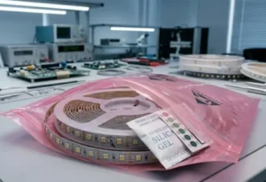
Traceability Labels
Walk over to the packaging area. Look at the labels on the reels. A good label should list more than just voltage and power. It should have a Batch Number and a Bin Code. This data must link back to their ERP system. If the label is generic, you have no way to trace a defect back to the production date or raw material batch.
MacAdam Ellipse Tolerance Levels
| MacAdam Step (SDCM) | Visual Perception | Typical Application |
|---|---|---|
| 1-Step | No visible difference | Laboratory / Precision Medical |
| 3-Step | Barely visible variance | High-end Hotels / Museums |
| 5-Step | Noticeable variance | General Residential / Street Light |
| 7-Step | Obvious difference | Low-cost decoration |
What aging and reliability testing equipment must I see to validate the factory's quality claims?
Our team never approves a new supplier until we have physically walked through their aging room and verified that the racks are fully powered and monitoring real-time data, rather than just acting as temporary storage.
You must confirm that the factory performs a 100% burn-in test for at least 12–24 hours on all finished reels and inspect their reliability lab for salt spray chambers, programmable temperature-humidity ovens, and mechanical bending testers.

A shiny production line produces the product, but the testing room proves it will last. Many factories skip rigorous testing to save electricity and time. You need to ensure they are not cutting corners here.
The Aging Room (Burn-In Test)
This is usually a warm room filled with racks of glowing LED strips.
- Is it ON? It sounds silly, but check if the lights are actually powered.
- Timeframe: Ask how long they run the aging test. For COB strips, 4 to 8 hours is common for standard orders, but for project-grade, we insist on 12 to 24 hours.
- Voltage Cycling: The best aging racks switch the power on and off rapidly (shock testing) to stress the components, rather than just leaving them on continuously.
The Reliability Lab
Beyond the standard aging room, there should be a separate laboratory for destructive testing. This is where they test the limits of the materials.
- Salt Spray Tester: Essential if you are buying IP65, IP67, or IP68 waterproof strips. IP65, IP67, or IP68 10 It simulates coastal environments to check for corrosion.
- Temperature & Humidity Chamber: This box cycles between extreme heat (e.g., +80°C) and freezing cold (e.g., -40°C). This ensures the silicone won't yellow or crack in harsh climates.
- Torsion/Bending Tester: This machine repeatedly bends the strip. COB strips are flexible, but the internal copper traces can break if the design is poor. This machine counts how many bends the strip can survive before failure.
Validating the Data
Don't just look at the machines; ask for the logbook. A machine that is turned off and covered in dust is a bad sign. You want to see recent entries in the testing logs. If the last entry was three months ago, they are not testing regular batches.
Conclusion
Conducting an on-site inspection in China is about peeling back the marketing layers to see the engineering reality. By focusing your audit on die bonding precision, soldering profiles, color consistency systems, and rigorous aging protocols, you protect your business from the reputational damage of product failure. It is not just about finding faults; it is about finding a partner whose process you can trust.
Footnotes
- General background on COB technology and its manufacturing advantages. ↩︎
- Research on the chemical composition and application of LED coatings. ↩︎
- Technical specifications for high-flexibility copper used in flexible circuits. ↩︎
- Leading manufacturer explaining Automated Optical Inspection technology. ↩︎
- Scientific standard for measuring color consistency and human perception. ↩︎
- Official definition and measurement standards for color quality in lighting. ↩︎
- Major manufacturer documentation on LED binning and labeling standards. ↩︎
- Technical explanation of how light output and color are measured. ↩︎
- Authoritative educational resource defining color matching metrics. ↩︎
- Official international standard body for Ingress Protection ratings. ↩︎