Dealing with flickering lights or dark spots on a complex curved cove installation is a nightmare, especially when your supplier is thousands of miles away. We see contractors struggle with these issues daily in our export department because the initial technical alignment was skipped.
To seek effective support, establish direct engineer access via apps like WeChat for real-time video troubleshooting. Provide comprehensive CAD files and demand custom voltage drop maps before production. Always verify the supplier can offer specific heat dissipation data and pre-assembled harnesses to minimize on-site risks.
Let's break down the exact steps to ensure your complex lighting project succeeds without costly delays.
What specific project details should I send to get an accurate technical solution?
Vague emails often lead to costly production errors that our engineering team has to fix later when the goods arrive on site. Sending just a total length requirement is never enough for irregular shapes or custom designs.
You must send detailed CAD drawings, DIALux lighting simulations, and environmental specifications including temperature ranges. Explicitly state the mounting substrate material for thermal analysis and provide a clear control protocol requirement to ensure the driver and COB strip compatibility matches your site’s electrical infrastructure.
To get a precise solution from a manufacturer, you must move beyond basic product codes. In our daily operations, we prioritize projects that arrive with a complete data pack because it allows us to run simulations before a single LED chip is mounted. For complex or irregular installations—such as curved bulkheads or non-linear architectural features—the physical geometry dictates the electrical layout.
Essential Documentation for Analysis
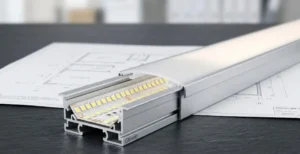
When you provide a CAD (.dwg) file or a SketchUp model SketchUp 1, it allows the engineering team to calculate the precise bend radius required. COB (Chip on Board) strips are flexible, but they have physical limits. If a curve is too tight, the PCB (Printed Circuit Board) can crack. Printed Circuit Board 2 By analyzing your drawings, we can determine if you need a specific 8mm or 5mm wide PCB, or if a "zigzag" bendable strip is more appropriate for your shape.
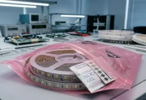
Furthermore, environmental context is non-negotiable. We often see failures where a standard IP20 strip was specified for a "dry" area that actually experiences high humidity or salt mist, leading to corrosion. You must specify the ambient temperature ambient temperature 3 and the material you are mounting to (e.g., wood, drywall, or aluminum). This data allows suppliers to simulate heat dissipation. If the substrate cannot absorb the heat generated by a high-wattage COB strip, the phosphor will degrade, shifting the color temperature over time. color temperature 4
The Role of Lighting Simulations
Providing a DIALux simulation helps the supplier match the lumen output DIALux simulation 5 to your target lux levels. If you don't have this, ask the supplier to run it. We frequently adjust the LED density (e.g., moving from 320 LEDs/m to 480 LEDs/m) based on these simulations to ensure the light is dot-free and sufficiently bright for the specific ceiling height.
| Document Type | Why It Is Critical | Consequence of Omission |
|---|---|---|
| CAD / Vector Drawings | Defines exact lengths, angles, and bend radii. | Strips may be too long, requiring risky on-site cutting, or fail to bend around corners. |
| DIALux Simulation | Verifies lux levels and uniformity. | The final result may be too dim or cause glare, leading to client rejection. |
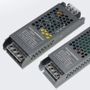
| Control Protocol Specs | Confirms compatibility (DALI, DMX, Zigbee). | Flickering lights, dimming issues, or complete lack of control response. |
| Thermal/Mounting Specs | Determines heat dissipation needs. | Overheating reduces lifespan and causes color shift (yellowing) within months. |
Can the manufacturer assist with wiring diagrams for my non-standard COB strip layout?
Voltage drop causes dim ends in long runs, a common complaint we help resolve during the design phase to protect our brand reputation. Without a proper map, installers often guess the injection points, leading to uneven lighting.
Yes, reputable manufacturers can generate custom wiring diagrams identifying exact power injection points based on your total run length. They should calculate voltage drop for non-linear layouts and recommend specific parallel wiring strategies or loop circuits to ensure uniform brightness across the entire installation.

One of the biggest advantages of working directly with a factory rather than a generic trader is access to electrical planning. For irregular installations, standard wiring rules often fail. When we analyze a project with multiple twists, turns, and long continuous runs, the primary enemy is voltage drop voltage drop 6. This is where the brightness at the end of the strip is visibly lower than at the start.
Custom Voltage Drop Maps
A professional supplier should provide a "Voltage Drop Map." This is a diagram that marks exactly where power needs to be injected. For a standard 24V COB strip, you generally cannot exceed 5 meters in a single series run without visible dimming. However, for irregular shapes that might wrap around a large column or weave through a ceiling feature, you might need a 20-meter run.
In these cases, we calculate the resistance based on the copper thickness of the PCB (usually 2oz or 3oz for high-end projects) and the load. The solution often involves running a parallel main wire alongside the strip and injecting power every 5 meters, or using a "loop circuit" where power connects to both the head and tail of the run.
Pre-assembled Wiring Harnesses
To reduce labor costs and errors, ask for pre-assembled wiring harnesses. Instead of your electrician soldering wires on a ladder, the factory can produce "octopus" cables or daisy-chain connectors cut to the exact lengths required by your layout. This "plug-and-play" approach drastically reduces the risk of polarity reversals or cold solder joints on site.
Understanding Wiring Topologies
Different shapes require different wiring strategies. A simple linear run is easy, but a branching irregular shape requires careful load balancing.
| Wiring Method | Description | Best Application | Pros & Cons |
|---|---|---|---|
| Single End Feed | Power enters one end only. | Short runs (<5m for 24V). | Pro: Simple. Con: High risk of voltage drop on long runs. |
| Dual End Feed (Loop) | Power enters both start and end. | Medium runs (5-10m). | Pro: Doubles max length, uniform light. Con: Requires return wire routing. |
| Center Feed | Power enters the middle of the strip. | Symmetrical layouts. | Pro: Balanced distribution. Con: Hard to hide wire in the middle of a visible run. |
| Parallel Injection | Main line runs alongside; power injected every 5m. | Long, irregular perimeters (>10m). | Pro: Unlimited length consistency. Con: Higher cabling cost and installation time. |
How do I know if the supplier supports custom cutting and soldering for irregular shapes?
Trying to solder tiny pads on a ladder is risky; our production line uses automated robots to ensure perfect joints every time. Hand soldering on-site frequently fails, causing dead sections that look unprofessional.
Verify if the supplier offers automated soldering services for custom lengths and shapes during the inquiry stage. Ask for photos of their specific soldering equipment and request "Single Bin" selection to guarantee color consistency across different cut segments of your irregular design.
For irregular installations, standard 5-meter rolls are rarely sufficient. You will likely have segments that need to be 3.2 meters, 1.5 meters, or even 45 centimeters. If you rely on cutting and soldering these on-site, you introduce a massive variable for failure. Hand soldering on flexible PCBs is delicate; too much heat lifts the copper pad, and too little creates a "cold joint" that breaks after a few months of thermal expansion and contraction.
Factory vs. On-Site Customization
When we process orders for high-end projects, we use automated soldering machines. These machines control the temperature and solder amount to the microgram. You should confirm your supplier has this capability. Ask them: "Do you offer cut-to-length services with factory-soldered leads?"
If your design involves corners (e.g., a hexagon or a sharp 90-degree turn), ask for pre-soldered corner connectors. Bending a standard COB strip sharply will damage the internal circuitry. Factory-made L-shape or flexible jumper connections ensure the current flows smoothly without stressing the PCB.
The "Single Bin" Guarantee
Irregular shapes often mean multiple strips are installed close to each other. If one strip is slightly pinker and the next is slightly greener, the effect is ruined. This is known as MacAdam Ellipse variation MacAdam Ellipse 7. You must demand a "Single Bin" supply. This means all the LEDs for your project come from the exact same manufacturing batch, ensuring the color temperature (e.g., 3000K) is identical across all cuts.
Testing Supplier Capabilities
Before placing the bulk order, test their customization process. Ask for a sample customized to a weird length, like 1.23 meters with 50cm wire leads.
| Feature | On-Site Modification Risk | Factory Pre-Assembly Solution |
|---|---|---|
| Cutting to Size | Cutting wrong cut-points damages circuit. | Precision machine cutting at exact intervals. |
| Soldering Wires | Pad lifting, cold joints, short circuits. | Automated soldering with strain relief glue/silicone. |
| Waterproofing | Messy silicone application, leaks. | Professional injection molding or extrusion sealing (IP65/IP67). |
| Color Matching | Mixing batches leads to visible mismatch. | "Single Bin" management for the whole project lot. |
What is the most effective way to get remote troubleshooting help during installation?
Email chains are too slow when you are standing on a job site with a deadline and a crew waiting. Our support team prioritizes instant messaging apps to resolve urgent site issues immediately.
Establish a direct communication channel via WeChat or WhatsApp with a dedicated technical engineer, not just a sales rep. Share real-time photos and videos of the wiring and driver connections to allow immediate diagnosis of polarity issues, signal interference, or connection faults.

The reality of international sourcing is that your supplier cannot physically visit your site. However, the speed of support can make or break a project. In our experience, email is excellent for documentation but terrible for troubleshooting. By the time a reply comes, your contractors have gone home.
Leveraging Instant Messaging
China runs on WeChat. Even if you prefer email, installing WeChat gives you a direct line to the factory floor. When we support complex installs, we often create a project group chat that includes the sales rep, the buyer, and a technical engineer. This allows the buyer to upload a 10-second video showing a flickering strip. An engineer can often hear the "whine" of a mismatched dimmer or see a wiring fault instantly—something that would take ten emails to explain.
Protocol Compatibility Matrices
Complex installs often involve smart controls (DALI DALI 8, DMX, 0-10V). DALI, DMX, 0-10V 9 Troubleshooting these requires data, not guesses. If your lights are strobing or not dimming smoothly, the issue is usually a protocol mismatch between the master controller and the LED driver.
Effective support involves the supplier providing a "Compatibility Matrix." This document confirms that their specific COB strips and drivers have been tested with major control brands like Lutron Lutron 10, Philips Dynalite, or Control4. If they haven't tested it, ask them to send a sample driver to their lab for verification before you install 500 meters of it.
The "Golden Sample" Strategy
For large, irregular projects, keep a "Golden Sample"—a small setup that works perfectly—in your office. If the site installation fails, you can compare the site conditions against the Golden Sample to rule out product defects vs. installation errors (like voltage drop or loose neutrals).
Conclusion
Successfully sourcing COB LED strips for irregular installations requires shifting the relationship from "buying a product" to "engineering a solution." By providing detailed CAD and environmental data upfront, demanding custom wiring maps, utilizing factory customization services, and establishing real-time video support channels, you eliminate the most common risks. Your supplier should be your off-site technical partner, capable of visualizing your project’s complexity and delivering a system that installs seamlessly.
Footnotes
- Official website for the 3D modeling software mentioned. ↩︎
- General overview of PCB construction, materials, and mechanical properties. ↩︎
- NIST standards for temperature measurement and SI unit definitions for technical specifications. ↩︎
- General background on the concept of color temperature in lighting. ↩︎
- Official software for professional lighting design and technical simulations. ↩︎
- Authoritative guide on measuring voltage drop from a major industry manufacturer. ↩︎
- Definition of the specific color consistency metric mentioned. ↩︎
- Official website of the Digital Illumination Interface Alliance standards body. ↩︎
- Official industry body for the DALI lighting control protocol standards. ↩︎
- Official website of the major lighting control manufacturer cited. ↩︎