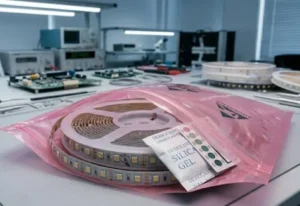
Walking through client sites, I often see panic over dead strips. Before assuming a bad batch from our site, take a breath. It is rarely the product itself.
To distinguish between defects and installation errors, perform a segment jump test and check continuity. If power reaches the input but the strip remains dark, bypass the controller and connect directly to the PSU. Installation faults usually affect entire runs, while product defects appear as isolated dead sections.
Let us break down the diagnostic process into simple steps to save your project timeline.
What are the most common wiring and polarity mistakes I should check before blaming the product?
When we assist contractors with troubleshooting, 70% of "failed" lights are just wired backward. It happens even to seasoned pros during rushed installs.
Common mistakes include reversing polarity at the power supply or connector, leading to a non-functional strip. Loose connections in solderless terminals often break the circuit. Always verify that the positive wire aligns with the positive PCB pad and that input voltage matches the strip's rating.

When a client calls us claiming a strip is "dead on arrival," we start with the basics. COB strips are diodes. They only allow COB strips are diodes 1 current to flow in one direction. COB strips are diodes 2 If you reverse the positive (+) and negative (-) wires, the strip will simply refuse to light up. It does not mean the strip is broken. It just means the flow of electricity is blocked.
The Polarity Trap
On a busy job site, lighting conditions are often poor. Our COB strips have very compact markings on the PCB due to the high density of the chips. It is easy to misread a small "+" or "-" sign. We always advise installers to trace the wire all the way back to the power supply unit (PSU). power supply unit (PSU) 3 Do not trust the wire colors alone. Sometimes, the red wire is not actually positive if it was wired incorrectly at the driver end.
Solderless Connector Failures
We see a rising trend in using solderless connectors for speed. However, COB strips have a layer of phosphor gel covering the chips. If you do not clear this gel properly or if the connector is slightly misaligned, the metal pins will not make contact with the copper pads. This creates an "open circuit." The power is there, but it cannot enter the strip.
Here is a checklist of common connection errors we encounter in our lab:
| Connection Issue | Visual Symptom | Recommended Fix |
|---|---|---|
| Reversed Polarity | Entire strip is dark; no flickering. | Swap the positive and negative wires at the PSU or controller. |
| Loose Terminal | Light flickers when the wire is touched or moved. | Re-strip the wire end and tighten the screw terminal firmly. |
| Misaligned Connector | Strip lights up intermittently or is dim. | Open the connector, align the PCB pads perfectly with pins, and snap shut. |
| Short to Aluminum | Driver shuts off immediately (protection mode). | Check if bare wires or solder points are touching the aluminum profile. |
Could an undersized power supply or voltage drop be the reason my COB strips are not working?
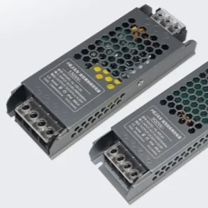
We design our high-voltage strips to handle long runs, but physics still applies. If a client uses a generic, underpowered driver, the lights will inevitably fail or flicker.
Yes, an undersized power supply triggers safety shut-offs, preventing the strip from lighting. Significant voltage drop occurs when wire gauges are too thin for the run length, causing dimming or total failure at the far end. Always ensure your driver capacity exceeds the total strip wattage by 20%.
Power issues are deceptive. Sometimes a strip lights up for a second and then goes dark. This is usually the power supply's internal protection kicking in. It senses an overload and cuts the power to save itself. This is not a defect in the LED strip; it is a system design error.
The 20% Headroom Rule
We strictly advise our partners to leave a safety margin. safety margin 4 LED strips can draw more power during startup or when running hot. If your total strip wattage is 100W, do not use a 100W driver. You need at least 120W. If the driver is maxed out, it will overheat and fail, or it will simply refuse to turn on. We often see this when designers add "just one more meter" to a run without upgrading the PSU.
Recognizing Voltage Drop
Voltage drop is another silent killer. COB strips Voltage drop is another silent killer 5 are sensitive. Voltage drop 6 If you run 24V from the source, but only 20V reaches the strip due to long, thin wires, the LEDs might not light up at all. Or, they might look orange and dim at the end. This is common in large commercial projects where the driver is hidden far away in a ceiling cavity.
We use the following table to help estimators plan their power needs correctly:
| Total Strip Wattage | Minimum Recommended PSU | Wire Gauge (up to 5m run) | Likely Consequence of Undersizing |
|---|---|---|---|
| 60 Watts | 75 Watts | 20 AWG | PSU overheats; strip flickers. |
| 100 Watts | 120 Watts | 18 AWG | PSU shuts down; no light. |
| 200 Watts | 240 Watts | 16 AWG | Voltage drop; end of strip is dim. |
| 300 Watts | 360 Watts | 14 AWG | Fire hazard in wires; rapid PSU failure. |
How can I tell if I accidentally damaged the PCB by cutting or bending the strip incorrectly?
Seeing a creased PCB in a return box hurts our engineering team. COB strips are flexible, but sharp folds snap the microscopic internal copper traces instantly.
Inspect the strip for sharp creases, punctures, or cuts made away from the designated solder pads. Physical damage often breaks the internal circuit, causing specific sections to fail while others work. If pressing on a damaged area briefly restores light, the copper trace is fractured.
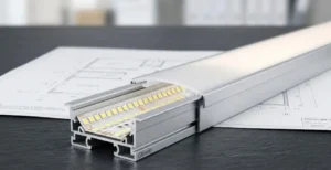
COB technology mounts chips directly onto the board COB technology 7, which makes the strip look seamless. COB technology 8 However, this also makes the circuit traces very dense. Physical trauma is the leading cause of "dead sections" we receive for warranty claims. warranty claims 9
The Danger of Sharp Bends
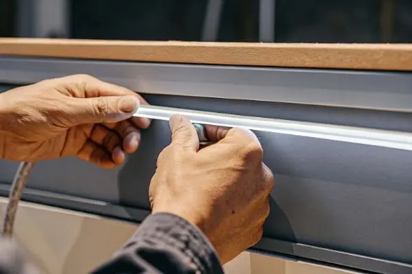
Installers often try to force strips around 90-degree corners without using corner connectors. If you fold an LED strip like a piece of paper, you break the copper pathways inside the PCB. This damage is permanent. You might see the first half of the strip light up perfectly, while the section after the corner remains dead. This is a clear sign of installation damage, not a manufacturing defect.
Precision Cutting is Vital
Every LED strip has specific cut points, usually marked by a copper line or a scissor icon. If you cut the strip anywhere else, you sever the circuit for that entire segment. We often see cuts made just a few millimeters off the mark. This leaves a "dead" tail on the previous segment and a "dead" head on the next one.
To confirm physical damage, we recommend a visual inspection of the PCB surface. Look for:
- Creases: White stress lines across the orange/yellow phosphor.
- Cracks: Visible breaks in the side of the PCB.
- Punctures: Marks from screwdrivers or installation tools.
If you find these marks exactly where the light stops working, the issue is physical trauma. The good news is that you can often cut out the damaged section and solder the remaining parts back together, saving the rest of the roll.
What specific multimeter tests can I run to confirm if the LED strip has an internal manufacturing defect?
When visual checks fail, we rely on data. A simple multimeter reading can settle a dispute between a contractor and a supplier simple multimeter reading 10 in less than five minutes.
Use a multimeter to measure voltage at the strip's input and continuity across the rails. Zero voltage indicates a supply issue, while a short circuit beep suggests an internal defect. Testing resistance helps isolate whether the failure is a dead PCB trace or a loose external connection.
If you have verified the wiring and the power supply, and the strip still looks perfect visually but won't light, it is time to measure. A multimeter gives us the "truth" that our eyes cannot see.
Input Voltage Verification
First, set your multimeter to DC Voltage. Place the probes on the solder pads where the wires connect to the strip.
- Reading matches PSU (e.g., 24V): Power is reaching the strip. If it is not lighting, the defect is likely internal to the strip.
- Reading is 0V or very low: The power is not getting to the strip. The issue is upstream—check your driver, dimmer, or wires.
Continuity and Resistance Checks
Set the multimeter to Continuity mode (the icon that looks like sound waves). Touch the positive and negative pads simultaneously.
- Beep sound: This indicates a short circuit. The positive and negative rails are touching somewhere. This could be a manufacturing defect (bad solder) or an installation error (a screw piercing the strip).
- No sound: This is normal for a functional strip (unless it is powered, do not test continuity on a powered strip).
We use these readings to categorize the problem quickly:
| Test Location | Multimeter Mode | Reading | Diagnosis |
|---|---|---|---|
| PSU Output | DC Voltage | 0V | Power Supply Failure or Breaker Tripped. |
| Strip Input | DC Voltage | 24V (but no light) | Internal Strip Open Circuit (Defect or Break). |
| Strip Input | DC Voltage | 10V (on 24V strip) | Voltage Drop or Overloaded Driver. |
| Strip Input | Resistance / Continuity | "Beep" (Short) | Internal Short Circuit (Reject Product). |
These tests are non-destructive and provide concrete evidence. If you find input voltage is perfect but the strip is dark, you have a valid warranty claim.
Conclusion
Systematic troubleshooting saves time and protects your reputation. Check your wiring first, verify power, and inspect for damage before claiming a warranty defect.
Footnotes
- Authoritative explanation of diode characteristics from a leading test equipment manufacturer. ↩︎
- Explains the semiconductor nature of LEDs and why polarity matters in electrical circuits. ↩︎
- Provides technical context for selecting and understanding industrial power supplies for LED systems. ↩︎
- Official guidance on energy efficiency and operational safety for LED lighting installations. ↩︎
- Technical overview of voltage drop phenomena in electrical engineering contexts. ↩︎
- Technical standard explaining the reduction in voltage as current moves through a conductor. ↩︎
- Definition of the specific LED manufacturing process mentioned in the text. ↩︎
- Background on the manufacturing process of mounting chips directly to a substrate. ↩︎
- Legal guidance on federal warranty laws for consumer and business products. ↩︎
- Educational resource on the functions and applications of digital multimeters in troubleshooting. ↩︎