Receiving a new shipment of lighting components is exciting, but hidden defects can disastrously delay project timelines. We always advise our partners to perform a structured incoming inspection structured incoming inspection 1 to prevent costly rework later.
To inspect COB LED strips upon arrival, first examine the external packaging for shipping damage. Next, visually check internal reels for bent PCBs or moisture. Safely power on the unspooled strips to verify color consistency, and finally cross-reference voltage and wattage specifications against your order documentation.
By following a standardized unboxing protocol, you protect your investment and ensure the installation phase proceeds without interruption.
What visual checks should I perform on the packaging and reels to identify potential shipping damage?
We pack our crates to withstand the rigors of global logistics, but rough handling by carriers is an unavoidable reality. Ignoring crushed corners or pierced boxes often leads to discovering microscopic PCB fractures during installation.
Inspect the outer box for crushing, water stains, or puncture marks immediately upon delivery. Inside, verify the moisture barrier bag is vacuum-sealed and the humidity indicator card is dry. Examine the reel for cracks and check the COB strip surface for yellowing or peeling, which indicates heat damage or poor storage.
External Packaging Analysis
The first line of defense is the cardboard carton. When our warehouse team prepares an order, we look for structural integrity, but the journey from the factory to your site can be harsh. Before you even cut the tape, look for "shock" signs. If a corner is accordion-crushed, the reels inside may have suffered impact damage. This is critical for COB strips because the flip-chip technology is directly bonded to the board; a hard impact can crack the solder joints without visible external damage.
Check for water stains or "tide marks" on the cardboard. LED strips are sensitive electronic components. If the outer box shows signs of having been wet, moisture may have penetrated the inner layers, leading to potential corrosion on the copper pads long after installation.
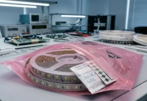
Internal Reel and Bag Inspection
Once the box is open, do not immediately rip open the silver anti-static bags. Look at the vacuum seal. Is it tight against the reel? A loose bag suggests a puncture, meaning the strips have been exposed to ambient humidity. For B2B projects where strips might sit in storage for months, this seal is vital.
Inside the bag, look for the Desiccant and Humidity Indicator Card humidity indicator card 2. If the dots on the card have changed color (usually from blue to pink), the internal environment is compromised.
Physical Strip Examination
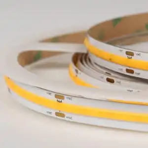
Carefully remove the reel and inspect the strip itself. COB strips feature a continuous phosphor coating. phosphor coating 3 You are looking for:
- Cracks in the Coating: If the yellow phosphor layer is cracked, you will likely see a "blue leak" of light when powered.
- PCB Delamination: Check the edge of the strip. The copper layers should not be peeling away from the substrate.
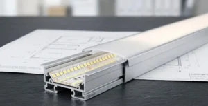
- Adhesive Gaps: The 3M tape on the back must be flush 3M tape 4. 3M tape 5 Air bubbles between the tape and the PCB can cause heat spots because the strip won't bond flat to the aluminum channel.
Visual Defect Checklist
| Component | What to Look For | Potential Consequence |
|---|---|---|
| Outer Box | Crushed corners, punctures, wet spots | Cracked solder joints, moisture ingress. |
| Static Bag | Loss of vacuum (loose bag), holes | Oxidation of copper contacts. |
| Reel Spool | Cracked plastic hub | Impact damage to the inner LED windings. |
| COB Surface | Hairline cracks in yellow phosphor | Blue light leakage, color inconsistency. |
| Backing Tape | Peeling liner, dried adhesive | Strip detachment, thermal failure. |
How do I safely power up the COB strips to test for color consistency and dark spots before installation?
In our aging room, we run strips for hours to ensure stability, but you need a quick verification method at your site. A common mistake we see is powering a coiled reel, which can melt the silicone coating instantly.
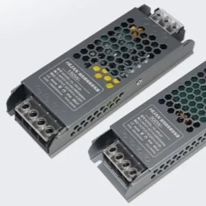
Unspool the strip loosely on a non-conductive surface to dissipate heat before applying power. Connect it to a compatible DC driver with 20% headroom to prevent voltage sag. Scan the entire length for dark sections, dead chips, or color shifting, and ensure the phosphor coating provides a seamless, dot-free light output.
Thermal Management During Testing
COB (Chip on Board) strips have a high density of chips, often exceeding 320 or 480 chips per meter. Chip on Board 6 This generates significant heat. When we test in the factory, the strips are typically flat. If you power up a 5-meter reel while it is still wound tight on the plastic spool, the heat cannot escape. The inner layers will rapidly heat up, potentially damaging the phosphor coating or even melting the spool.
Always unroll the strip. You do not need to stick it down; just laying it loosely on a clean, dry floor or table is sufficient. This allows air to circulate around the FPC (Flexible Printed Circuit) and keep the temperature within safe operating limits during your inspection.
The "Dark Spot" and Uniformity Check
Once powered, scan the length of the strip. You are looking for breaks in the light.
- Dead Sections: A completely dark segment (usually 25mm to 50mm) indicates a break in the circuit or a failed resistor. This is an immediate fail.
- Dim Sections: If one section is dimmer than the rest, it could indicate a poor solder joint or a damaged chip affecting the series circuit.
- Dotting: The selling point of COB is the "dotless" effect. If you can see individual points of light, the phosphor coating may be too thin, or the chip density is lower than what you ordered.
Assessing Color Consistency (MacAdam Ellipse)
For high-end projects, color consistency is non-negotiable color consistency 7. If you ordered 3000K, it needs to look like 3000K, not 3200K or 2800K.
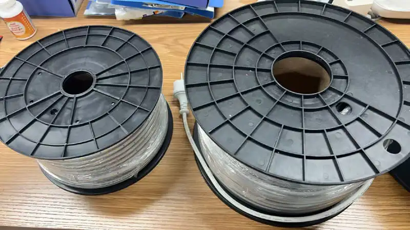
- Side-by-Side Test: Power up two or three reels from the same shipment side-by-side.
- White Paper Test: Hold a piece of white paper about 5cm above the strips. Look at the reflection on the paper. It is often easier to see color casts (green or pink tints) in the reflection than by looking directly at the blinding light source.
- Binning Verification: Check the batch codes. We produce strips in "bins" to ensure color matching. If you see visible differences, check if the reels came from different production batches.
Troubleshooting Common Power-Up Issues
| Symptom | Probable Cause | Action Required |
|---|---|---|
| Strip flickers | Loose connection or under-powered driver | Tighten terminals; check PSU wattage. |
| End of strip is dim | Voltage drop | Use a thicker gauge wire or 24V supply. |
| Yellow discoloration | Heat damage (powered while coiled) | Discard strip; do not install. |
| Color mismatch | Mixed bins/batches | Check labels; contact supplier immediately. |
How can I confirm that the voltage and wattage specifications match the project requirements I ordered?
Our engineers meticulously calibrate voltage drops for long runs, yet mix-ups occur in distribution warehouses. Installing a 12V strip on a 24V driver guarantees immediate failure, while the reverse results in dim lighting.
Check the printed markings on the FPC board every 0.5 meters for voltage ratings. Use a multimeter to measure power consumption over a specific length and compare it to the datasheet. Verify the copper thickness is sufficient to prevent significant voltage drop over long runs.

Verifying PCB Markings
The simplest check is often the most overlooked. We print the voltage (e.g., "DC24V") and the cut points directly on the Flexible Printed Circuit (FPC) board.
- Cut Points: Verify the distance between cut points. A 12V COB strip usually has a cut point every 25mm or 50mm, while a 24V strip might be every 50mm. This spacing must match your installation plan, especially for custom joinery work.
- Copper Weight: While you cannot "see" 2oz or 3oz copper, you can feel it. A high-quality strip with thicker copper (for better heat dissipation and less voltage drop) will feel stiffer and heavier than a cheap 1oz strip.
The Multimeter Test for Wattage
Datasheets give you a "rated wattage," but real-world physics involves resistance. To confirm you received the correct power density (e.g., 10W/m vs. 15W/m):
- Set up: Connect a multimeter multimeter 8 in series with the strip to measure Amps (Current).
- Measure: Power on a 1-meter length of the strip.
- Calculate: Use the formula $Power (W) = Voltage (V) \times Current (A)$.
- Example: If you have a 24V strip and measure 0.4 Amps over 1 meter, the wattage is $24 \times 0.4 = 9.6$ Watts/meter.
- Compare: Does this match your order? A variance of +/- 10% is standard in the industry. If you ordered 15W/m and measure 9.6W/m, you have received the wrong product, and the brightness will be insufficient for your project.
Voltage Drop Simulation
If your project involves long runs (e.g., 10 meters powered from one end), you must test for voltage drop before installation voltage drop 9.
- Connect the full length to power.
- Measure the voltage at the input pads (should be 24V).
- Measure the voltage at the very end of the strip.
- If the end voltage drops below 22V (on a 24V strip), you will see visible dimming. This confirms if the internal copper trace width is sufficient for the load.
Electrical Specification Verification Table
| Specification | How to Verify | Acceptable Tolerance |
|---|---|---|
| Input Voltage | Read PCB print; Multimeter DC Test | Must match exactly (12V/24V) |
| Power (Wattage) | Amperage reading calculation ($P=VI$) | +/- 10% of rated spec |
| PCB Width | Calipers (e.g., 8mm, 10mm) | +/- 0.2mm |
| Cut Interval | Tape measure between scissor marks | Exact match to datasheet |
What documentation should I gather if I discover quality issues or shortages during the unboxing process?
We value feedback to improve our production line, but vague complaints delay resolutions significantly. A documented claim with high-resolution photos allows us to trace the batch and authorize replacements trace the batch 10 immediately.
Photograph the shipping label, batch number, and specific damage clearly. Keep the original packaging and the QC certificate found inside the bag. Compile a report detailing the shortage amount or defect type, then submit this evidence to your supplier within the inspection window.

The "Chain of Evidence" for Claims
When a defect is found, the immediate reaction is often to discard the bad section. Do not do this. As a supplier, we need to trace the root cause. Was it a soldering robot error? A bad batch of phosphor? Or shipping damage?
To support your claim, you need a "Chain of Evidence":
- The Outer Box Label: This contains the tracking number and weight. If a box arrives light, this proves a shortage occurred before delivery.
- The Bag Label: This contains the Part Number (SKU) and critical specs (CCT, Voltage).
- The QC Pass Sticker: Usually a small slip inside the bag or a sticker on the reel. This often has a specific inspector's code or a production date.
Documenting Visual Defects
Blurry photos are the enemy of quick resolutions.
- Macro Shots: Use your phone's macro mode to take close-ups of cracked solder joints or LED chips.
- Wide Shots: Take a photo of the strip powered up to show the context of the failure (e.g., "Segment 3 is dark").
- Video: For flickering issues or color shifting, a 10-second video is worth a thousand emails. Move the camera slowly along the strip.
The Importance of Batch Numbers
The most critical piece of data is the Batch Number (or Lot Number). In professional LED manufacturing, we produce chips in massive runs. If you have a color consistency issue, telling us "It looks too green" is subjective. Telling us "Batch #20231015-A does not match Batch #20231102-B" allows us to pull the retention samples from our warehouse and verify the error scientifically. This is how we ensure your replacement strips match the ones you have already installed.
Claim Submission Checklist
| Document/Item | Purpose | Why it is Critical |
|---|---|---|
| Commercial Invoice | Proof of purchase | Links product to specific transaction. |
| Photo of Batch Label | Production tracing | Identifies the specific manufacturing run. |
| Video of Defect | Dynamic proof | Proves flickering or intermittent faults. |
| Voltage Reading Photo | Technical proof | Proves the issue isn't your power supply. |
| Quantity Count | Shortage verification | Ensures credit is issued for missing length. |
Conclusion
Proper inspection protects your profit margins and reputation. By systematically checking packaging, testing functionality, verifying specs, and documenting any issues immediately, you ensure your lighting installation remains flawless and your project stays on schedule.
Footnotes
- International standard (ISO 2859) for sampling procedures during inspection. ↩︎
- JEDEC standard for handling moisture-sensitive devices. ↩︎
- Scientific background on the phosphor materials used to convert LED light into white light. ↩︎
- Official manufacturer documentation for the specific adhesive product. ↩︎
- Official manufacturer documentation for the adhesive tape commonly used on LED strip backings. ↩︎
- General background information on the semiconductor assembly technology used in COB LED strips. ↩︎
- Department of Energy guide on LED color metrics. ↩︎
- Technical documentation from a major manufacturer on correctly measuring current in electronic circuits. ↩︎
- Industry leader guide explaining electrical voltage drop. ↩︎
- Global standards organization for supply chain traceability. ↩︎