
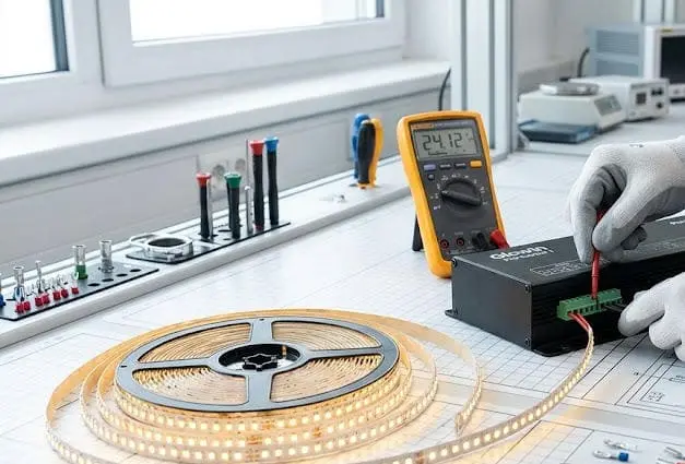
Мы видим возвращённые светодиодные ленты, которые работали идеально — до тех пор, пока кто-то не подключил их к неправильному контроллеру или пропустил базовую проверку напряжения.
Чтобы настроить и протестировать светодиодные ленты с контроллером, сначала необходимо подобрать тип ленты и напряжение, совместимые с контроллером и блоком питания, правильно подключить положительные и цветовые клеммы, синхронизировать пульт или приложение, а затем выполнить полный тест функций перед постоянной установкой.
Процесс прост, но каждый шаг содержит моменты, когда можно тихо ошибиться Совмещение напряжения 1. Ниже я расскажу о процессе подключения, тестирования, устранения неисправностей и синхронизации, который мы рекомендуем каждому подрядчику и оптовому покупателю, приобретающему нашу продукцию. Правильная последовательность поможет избежать повторных вызовов, потраченных лент и разочарованных клиентов.
Как правильно подключить светодиодные ленты профессионального уровня к контроллеру?
Ошибки при подключении вызывают большинство отказов светодиодных лент, которые мы видим по гарантии — и почти все из них можно предотвратить с помощью четкого процесса Система управления DMX512 2.
Подключите ваши светодиодные ленты к профессиональному контроллеру, соединяя маркированную положительную площадку ленты с клеммой V+ контроллера, затем сопоставьте каждый цветовой канал (R, G, B или W) с соответствующей клеммой контроллера, и, наконец, подключите вход контроллера к блокy питания с подходящим напряжением.
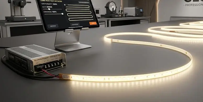
Знайте тип вашей ленты, прежде чем трогать провод
Не все светодиодные ленты используют одинаковую схему подключения. Одноцветная лента имеет всего два провода: положительный и отрицательный. А RGB лента 3 имеет четыре: V+, R, G и B. RGBW лента добавляет пятый провод для выделенного белого канала. Адресные ленты 4 такие как WS2812B используют совершенно другой протокол передачи данных.
Если подключить RGB ленту к диммеру для одноцветных, будет реагировать только один канал. Если подключить RGBW ленту 5 к RGB контроллеру, полностью потеряется белый канал. Первое правило простое: подтвердите тип ленты, а затем выберите контроллер, который ей соответствует.
Чтение печатных меток на ленте
Наша инженерная команда всегда говорит клиентам одно и то же: доверяйте меткам, напечатанным на полоске, а не цветам изоляции проводов. Мы видели, как монтажники предполагают, что красный провод всегда положительный или что зеленая изоляция всегда несет зеленый сигнал. Такое предположение приводит к инвертированным каналам или мертвым полоскам. Переверните полоску. Прочтите шелкографию. Там будет что-то вроде V+, R, G, B. Эти метки — ваш надежный источник информации.
Пошаговая схема подключения терминалов
Вот базовая последовательность подключения для RGB-настройки:
| Шаг | Действие | Деталь |
|---|---|---|
| 1 | Обрежьте концы проводов | Обнажите 5–7 мм оголенного медного провода; не оставляйте изоляцию внутри клеммы |
| 2 | Вставьте провод V+ в клемму V+ контроллера | Плотно затяните винт на оголенном медном проводе |
| 3 | Вставьте провод R в клемму R контроллера | Совместите с напечатанной площадкой R на полоске |
| 4 | Вставьте провод G в клемму G контроллера | Совместите с напечатанной площадкой G на полоске |
| 5 | Вставьте провод B в клемму B контроллера | Совместите с напечатанной площадкой B на полоске |
| 6 | Подключите блок питания 6 к входу постоянного тока контроллера | Совпадение напряжения: полоска 12V использует источник 12V, полоска 24V — источник 24V |
| 7 | Дважды проверьте полярность перед включением питания | Положительный к положительному, отрицательный к отрицательному |
Соответствие напряжения не подлежит обсуждению
Когда мы отправляем комплекты образцов новым партнерам в России или Австралии, мы всегда прилагаем памятную карточку: проверьте напряжение. Светодиодная лента на 12 В при питании от 24 В быстро перегреется и сгорит. Светодиодная лента на 24 В при питании от 12 В едва будет светиться. Блок питания должен выдавать точно такое же номинальное напряжение, как и у ленты, — без исключений.
Разъемы против пайки
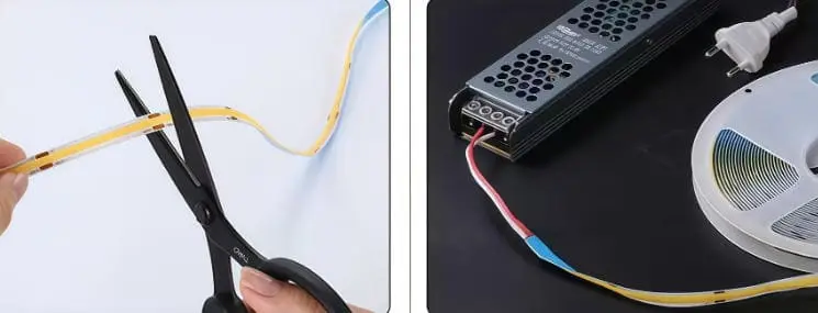
Для быстрой прототипирования или временных тестовых установок отлично подойдут зажимные разъемы. Но для постоянных коммерческих инсталляций пайка или надежно затянутые винтовые клеммы гораздо надежнее. Мы видели, как зажимные разъемы со временем ослабевают от термическое циклирование 7, особенно в нишах потолка, где температура колеблется. Для любого проекта, который должен прослужить годы без вызовов сервисной службы, пайка или винтовые клеммы — это правильный выбор.
Какие шаги мне следует выполнить, чтобы проверить цветовую согласованность и стабильность затемнения моей установки?
На нашей линии контроля качества каждая катушка проходит проверку на однородность цвета перед отправкой. Вам следует сделать то же самое на месте перед тем, как приступить к постоянной установке.
После подключения включите ленту и протестируйте каждый цветовой канал по отдельности на полной яркости, затем на 25%, 50% и 75% уровнях. Проверьте равномерность цвета по всей длине, плавность перехода при затемнении и отсутствие мерцания при низкой яркости, чтобы подтвердить стабильную работу.
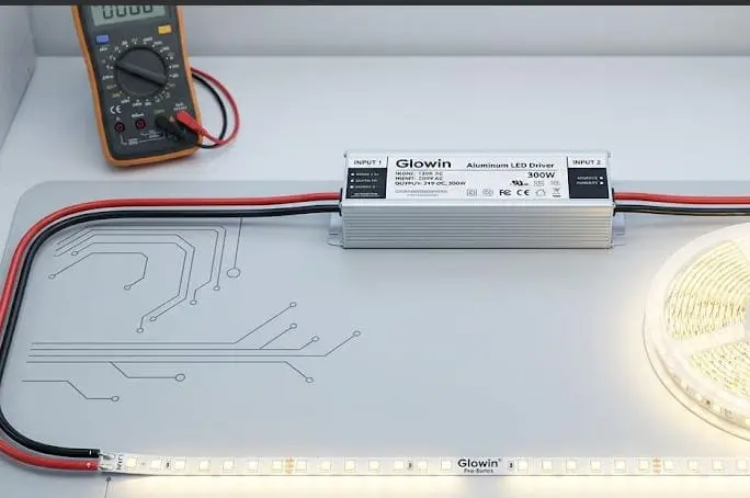
Зачем тестировать перед монтажом
Светодиодные ленты с клейкой основой, по сути, одноразовые после монтажа. Если вы приклеите ленту к алюминиевому профилю, проложите ее по 10-метровой потолочной нише, а затем обнаружите, что цвета смещаются на дальнем конце, вас ждет дорогостоящий демонтаж. Тестирование на столе занимает пять минут. Переделка занимает часы.
Тест цветовых каналов
Включите каждый канал — красный, зеленый, синий — поочередно. Проверьте равномерность яркости от первого светодиода до последнего. Если красный канал яркий у контроллера, но тускнеет на дальнем конце, у вас, вероятно, есть падения напряжения 8 проблема. Если зеленый канал вообще не загорается, перепроверьте клемму. Этот тест одного канала быстро выявляет ошибки подключения.
Тест стабильности затемнения
Не все контроллеры плавно затемняют. Некоторые используют широтно-импульсную модуляцию (ШИМ) 9 с частотами, слишком низкими для человеческого глаза, вызывая видимое мерцание — особенно на камере. Вот как мы рекомендуем тестировать:
| Уровень затемнения | На что обращать внимание | Критерии прохождения |
|---|---|---|
| 100% | Полная яркость, равномерный цвет | Нет горячих точек, нет мертвых светодиодов |
| 75% | Незначительное снижение | Плавный переход, без смещения цвета |
| 50% | Средняя яркость | Нет заметной мерцания, равномерная яркость |
| 25% | Низкая яркость | Нет мерцания, нет шума от драйвера |
| 5–10% | Очень низкий | Плавное затухание, светодиоды остаются включенными без рывков |
Если вы замечаете мерцание при низких уровнях затемнения, частота ШИМ вашего контроллера может быть слишком низкой. Многие профессиональные контроллеры работают на частоте 1 кГц или выше, что исключает видимое мерцание. Бюджетные контроллеры иногда работают на частоте 200–500 Гц, и именно там начинаются проблемы — особенно в гостиничном или розничном секторе, где клиенты снимают видео на смартфоны.
Баланс белого и цветовая температура
Для RGBW или регулируемых по белому лент тестируйте белый свет при различных цветовых температурах. Обходите длину ленты и ищите сдвиги оттенков — иногда тёплый конец ленты слегка розовеет или зеленеет по сравнению с холодным концом. Это часто связано с несоответствием партии светодиодов, поэтому мы сортируем наши светодиоды по строгим бин-степеням МакАдама 10 перед сборкой. Если вы замечаете несоответствия, возможно, сама лента должна быть заменена на более однородную партию.
Тестирование режима и сцены
Переключайтесь между несколькими предустановленными режимами на контроллере: статический цвет, плавное изменение цвета, скачки цвета и любые пользовательские сцены. Подтвердите, что переходы плавные и что лента реагирует в течение одной секунды на каждую команду. Задержка в ответе может указывать на проблему с прошивкой контроллера или перегрузку линии данных на управляемых лентах.
Запишите свои результаты
Для коммерческих проектов ведите простой журнал ваших тестовых результатов. Записывайте дату, номер партии полоски, модель контроллера, модель блока питания и статус прохождения/непрохода каждого теста. Эта документация поможет вам в случае подачи гарантийного заявления или если клиент запросит подтверждение ввода в эксплуатацию.
Как я могу устранить проблемы с помехами сигнала или падением напряжения во время первоначального теста?
Когда мы проводим демонстрации длинных лент в нашем шоуруме — иногда 20 метров или больше — первым проявляющимся дефектом является падение напряжения. Следом за ним идет помеха сигнала, особенно в зданиях, заполненных другим электронным оборудованием.
Для устранения падения напряжения измерьте напряжение на дальнем конце ленты мультиметром; показание более чем на 0,5В ниже номинального напряжения указывает на необходимость параллельной проводки, использования более толстого провода или усилителя. Для устранения помех сигнала заземляйте кабели данных и отделяйте их от линий переменного тока высокого напряжения.
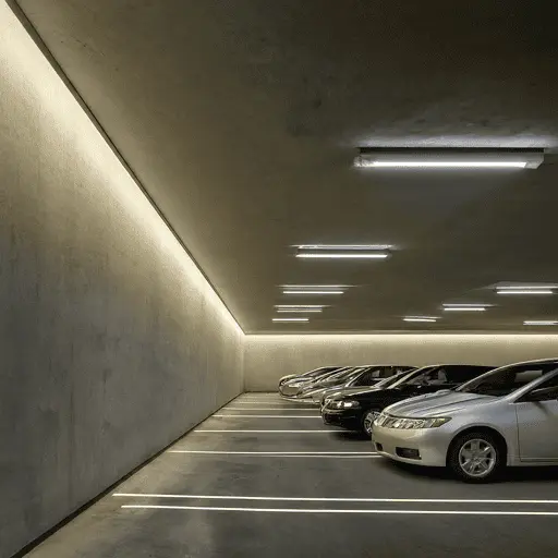
Понимание падения напряжения
Падение напряжения происходит потому, что медный провод имеет сопротивление. Чем длиннее провод и тоньше проводник, тем больше вы теряете напряжения между блоком питания и дальним концом ленты. На 12В ленте даже падение на 1В означает снижение доступного напряжения на 8%. Это приводит к более тусклым светодиодам, смещенной цветовой температуре и видимым градиентам яркости вдоль ленты.
Как измерить падение напряжения
Возьмите простой мультиметр. Установите его на постоянное напряжение (DC). Измерьте на входе питания ленты — должно показывать около 12В или 24В. Затем измерьте на дальнем конце. Если разница превышает 0,5В, необходимо принять меры.
| Симптом | Вероятная причина | Решение |
|---|---|---|
| Лента тускнеет к дальнему концу | Падение напряжения при длинной прокладке | Используйте параллельную проводку или подавайте питание с обоих концов |
| Цвета смещаются от белого к теплому на дальнем конце | Недостаточное напряжение для синих светодиодов | Используйте провод с более толстым сечением (например, 18 AWG вместо 22 AWG) |
| Мерцание ленты только на дальнем конце | Пограничное напряжение вызывает прерывистую работу светодиодов | Добавьте усилитель светодиодов в середине |
| Вся лента тусклая | Блок питания недостаточно мощный для общей нагрузки ленты | Рассчитайте общую мощность и обновите блок питания с запасом в 20% |
| Произвольные сбои цвета на адресных лентах | Ухудшение сигнала на расстоянии | Используйте усилитель сигнала или укороченные кабельные линии передачи данных |
Параллельное подключение против последовательного подключения
Большинство светодиодных лент подключены внутри в последовательной цепи. При увеличении длины увеличивается сопротивление. Решение — подавать питание с нескольких точек — это называется параллельным подключением питания. Проведите отдельную пару силовых проводов от источника питания к середине и к дальнему концу ленты. Это обеспечивает стабильное напряжение по всей длине. На нашем заводе при заказах длиной более 10 метров заранее отмечены точки подачи питания.
Помехи сигнала на адресных лентах
Адресные светодиодные ленты — такие как WS2812B или SK6812 — используют цифровую линию данных. Этот сигнал уязвим к электромагнитным помехам (ЭМИ) от соседних кабелей переменного тока, моторов или импульсных блоков питания. Симптомы включают случайное мигание, неправильные цвета или неотзывчивость части ленты.
Чтобы снизить помехи, держите линию данных физически отделенной от кабелей переменного тока как минимум на 15 см. Используйте экранированный кабель для длинных линий данных. Добавьте резистор 220–470 Ом в линию данных на выходе контроллера. Разместите конденсатор 1000 мкФ на входе питания первой светодиодной ленты для поглощения скачков напряжения.
Когда использовать усилитель
Усилитель для светодиодов повторяет сигнал контроллера и обеспечивает свежим питанием следующий сегмент ленты. Это необходимо для длинных линий, превышающих допустимую мощность контроллера. Например, если ваш контроллер рассчитан на 10 ампер, а общая нагрузка ленты составляет 15 ампер, вам нужен усилитель для перераспределения нагрузки. Усилитель принимает ШИМ-сигнал от контроллера и управляет дополнительным сегментом ленты от собственного источника питания.
Практический совет
Вот что мы узнали от подрядчика из Москвы, столкнувшегося с постоянным мерцанием при установке RGBW длиной 15 метров. Он использовал кабель 22 AWG для всей линии. Переключение на кабель 18 AWG и добавление подачи питания на 8-м метре полностью устранили проблему. Более толстый кабель и короткие линии питания решают большинство проблем с падением напряжения без усложнения системы.
Как синхронизировать несколько контроллеров для обеспечения равномерного освещения во всей коммерческой установке?
Один из самых распространенных вопросов, который мы получаем от наших партнеров-дистрибьюторов — особенно для больших залов отелей или торговых помещений — как сделать 50 метров ленты выглядящей как единая бесшовная линия, когда она фактически управляется тремя или четырьмя отдельными контроллерами.
Синхронизируйте несколько контроллеров светодиодов, используя конфигурацию мастер-слейв, систему управления DMX512 или централизованный Wi-Fi/Zigbee-хаб, который посылает единые команды всем контроллерам одновременно, обеспечивая одинаковый цвет, яркость и тайминг по всей установке.
Почему важна синхронизация
В жилых помещениях небольшие различия между двумя лентами могут остаться незамеченными. В коммерческих установках — например, в потолочном карнизе ресторана, коридоре отеля или витрине — любое несоответствие по цвету или таймингу сразу бросается в глаза. Клиенты замечают, когда одна секция чуть синее, чем следующая, или когда переход цвета начинается с задержкой в полсекунды на одном сегменте. Синхронизация — обязательна для профессиональных работ.
Конфигурация мастер-слейв
Многие профессиональные контроллеры светодиодов поддерживают режим мастер-слейв. Один контроллер выступает в роли мастера и отправляет свой сигнал одному или нескольким слейв-контроллерам через проводное соединение (часто простая двухпроводная или RJ45 связь). Все слейвы зеркалируют выход мастера в реальном времени. Это самый простой способ синхронизации и хорошо подходит для установок с менее чем пятью или шестью зонами.
Управление DMX512
Для больших или более сложных проектов стандартом индустрии является DMX512. Каждый контроллер получает DMX-адрес и реагирует на команды с центральной DMX-консоли или программного обеспечения. DMX поддерживает до 512 каналов на одну вселенную, что более чем достаточно для большинства проектов светодиодных лент. Преимущество DMX — точность: вы можете индивидуально адресовать каждый контроллер и программировать сложные сцены, плавные переходы и временные последовательности.
Беспроводная синхронизация
Некоторые современные контроллеры используют Wi-Fi, Zigbee или Bluetooth Mesh для синхронизации без проводов между устройствами. Центральное приложение или хаб отправляет команды всем контроллерам одновременно. Это хорошо подходит для ретрофит-проектов, где прокладка дополнительных управляющих проводов затруднена. Однако беспроводные системы могут вводить небольшую задержку — обычно 50–200 мс, что может быть заметно при быстрых цветовых переходах.
Выбор подходящего метода
| Метод | Лучше всего для | Плюсы | Минусы |
|---|---|---|---|
| Мастер-слейв (проводной) | Маленькие и средние установки, 2–6 зон | Простая настройка, надежность, отсутствие задержки | Требует физического проводного соединения между контроллерами |
| DMX512 | Крупные коммерческие установки, сложные сцены | Стандарт индустрии, точность, масштабируемость | Требуется DMX-консоль или программное обеспечение, более высокая стоимость |
| Wi-Fi / Zigbee Mesh | Ретрофиты, распределенные зоны | Отсутствие межконтроллерного проводного соединения, управление через приложение | Возможна задержка, зависит от стабильности сети |
| RF-пульт (групповой) | Бюджетные установки, базовая синхронизация | Низкая стоимость, не требуется сеть | Ограниченное управление сценами, менее точное синхронизирование по времени |
Обеспечение однородного цвета по зонам
Даже при идеальной синхронизации, если светодиодные ленты из разных партий производства, вы можете заметить небольшие различия в цвете. Поэтому мы тщательно сортируем и группируем наши светодиоды и рекомендуем подрядчикам заказывать все ленты для проекта из одной партии. Когда мы готовим заказы для многозонных проектов, мы берем катушки из одного производственного выпуска и включаем документацию по отслеживанию партии, чтобы монтажник мог проверить однородность на месте.
Практические советы по запуску системы
Начинайте с программирования одного контроллера и проверки его соответствия проектному замыслу. Затем скопируйте эти настройки на все остальные контроллеры. Запустите каждую сцену из плана освещения проекта и пройдите всю установку, чтобы обнаружить несоответствия. Используйте цветомер, если в спецификации проекта требуется количественная проверка однородности. В конце сохраните конфигурацию на основном контроллере или DMX-консоли, чтобы её можно было восстановить в случае замены контроллера.
Совместимость прошивки и протоколов
Убедитесь, что все контроллеры в проекте работают на одной версии прошивки и используют один и тот же протокол связи. Смешивание моделей контроллеров или версий прошивки — распространенная причина сбоев синхронизации. Когда мы поставляем комплекты с несколькими контроллерами, мы прошиваем все устройства одинаковой прошивкой перед отправкой, чтобы исключить этот фактор.
Заключение
Сначала правильно подключите проводку, затем протестируйте каждую функцию, прежде чем что-либо будет навсегда закреплено. Совпадите по напряжению, прочтите маркировку и проверьте каждый цветовой канал. Эта последовательность — подтверждение, подключение, тестирование, монтаж — предотвращает большинство отказов светодиодных лент, которые мы наблюдаем по всему миру.
Примечания
- Подчеркивает важность совпадения напряжения светодиодных лент с источником питания. ↩︎
- Объясняет DMX512 как стандартную цифровую сеть связи для управления освещением и эффектами. ↩︎
- Определяет RGB светодиодные ленты и то, как они создают цвета с помощью красных, зеленых и синих светодиодов. ↩︎
- Найден раздел на Википедии, объясняющий адресуемые RGB светодиодные ленты. ↩︎
- Объясняет RGBW светодиодные ленты, отмечая наличие дополнительного белого светодиода для более чистого белого света. ↩︎
- Объясняет роль, типы и выбор источников питания для светодиодных лент. ↩︎
- Нашел рабочую страницу Википедии, объясняющую тепловое циклирование. ↩︎
- Определяет падение напряжения как снижение электрического потенциала вдоль проводника из-за сопротивления. ↩︎
- Нашел рабочую страницу Википедии, объясняющую широтно-импульсную модуляцию (ШИМ). ↩︎
- Объясняет эллипсы МакАдама и шаги как меру цветовой разницы в светодиодных лампах для обеспечения однородности. ↩︎

 English
 Spanish
 German
 Russian
 Arabic
 French
 Portuguese