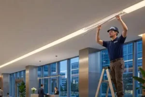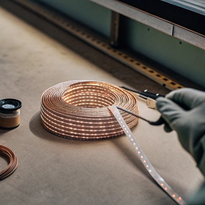
Simple LED strips routine check could have prevented the failure entirely from project sites.
A regular industrial LED strip light inspection checklist should cover electrical safety, physical mounting integrity, thermal condition, light output consistency, environmental protection (IP rating), connector condition, control system function, and documented maintenance records. This preventive approach catches fire risks, loose connections, and gradual performance degradation before they disrupt operations.
This article walks you through each critical inspection area. Whether you manage a warehouse, a commercial facade, or a large architectural installation, these checks will help you keep your LED strip systems reliable and safe for years. Let me break it down section by section.
How do I verify that my outdoor LED strips still maintain their IP rating and safety certifications?
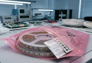
When we ship IP67 or IP68 strips 1 to projects in Australia and Germany, the seal integrity at installation is only half the story. What matters is whether that seal holds up six months or two years later.
To verify your outdoor LED strips still maintain their IP rating, inspect all gaskets, end caps, and silicone seals for cracks, yellowing, or separation. Check that certification labels remain legible. Look for moisture intrusion, fogging inside lenses, or corrosion at connectors. Any breach means the rating is compromised and the strip should be replaced or resealed.
Why IP Ratings Degrade Over Time
IP ratings are tested at the factory under controlled conditions. Once a strip is installed outdoors, UV exposure 2, temperature cycling, chemical contact, and physical stress all attack the sealing materials. Silicone can shrink. Adhesive can peel. End caps can loosen. Even a tiny crack in the outer jacket lets moisture creep in, and once moisture reaches the copper traces, corrosion starts. This is not a matter of if, but when. The question is whether you catch it early or after a section goes dark.
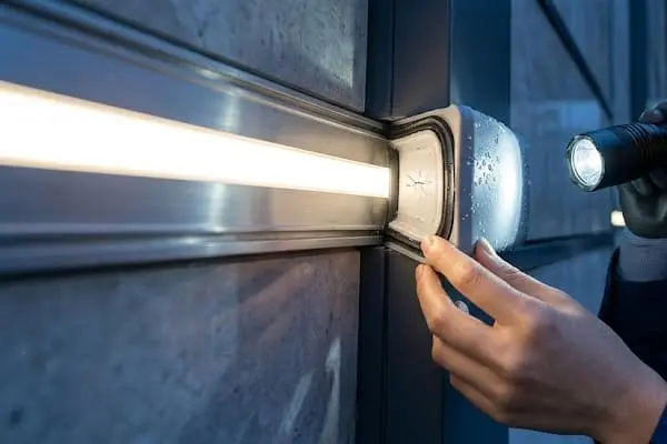
What to Look For During an IP Inspection
Start at one end of the strip run and walk the full length. Use a flashlight. Look closely at every junction point, every connector, and every end cap. Here is a practical checklist:
- Is there any visible condensation or fogging inside the silicone tube or lens cover?
- Are the end caps still firmly attached, or have they pulled away?
- Is the outer jacket cracked, yellowed, or brittle?
- Are any connector housings loose, corroded, or discolored?
- Can you still read the certification label 3 (CE, SAA, UL, etc.)?
- Is there any sign of water staining or mineral deposits on the strip surface?
Certification Label Check
In regulated environments, missing or illegible certification marks can be a compliance issue. If your project requires SAA approval in Australia or CE marking in Germany, the label must remain visible and readable. If it is gone, you need to document the replacement and ensure the new strip carries the same certification.
| Inspection Item | Pass Criteria | Fail Criteria |
|---|---|---|
| End cap seal | Firmly attached, no gaps | Loose, cracked, or missing |
| Outer jacket | Flexible, clear, no discoloration | Yellowed, brittle, cracked |
| Connector housing | Dry, clean, tight fit | Corroded, loose, moisture inside |
| Certification label | Legible, intact | Faded, peeled, or missing |
| Internal fogging | None visible | Condensation or water droplets inside |
| Surface deposits | Clean | Mineral stains or chemical residue |
When to Act
If you find any single fail item during the IP inspection, do not wait. Mark the section for repair or replacement. In our experience exporting to coastal Australian projects, even one compromised seal can lead to a full strip failure within weeks during a rainy season. Document the finding, photograph it, and schedule corrective action immediately.
What steps should I take to detect color consistency issues or light decay across my project site?
Color shift 4 and brightness loss are among the most common complaints we hear from distributors and contractors. The frustrating part is that these problems develop slowly, so they often go unnoticed until a client points them out.
To detect color consistency issues or light decay, compare adjacent strip sections under the same viewing conditions, measure lumen output with a light meter against baseline data, and look for visible differences in color temperature or brightness. Check for yellowed lenses, dirty diffusers, and sections from different production batches, which are leading causes of visual mismatch.
Understanding Why Color Shifts Happen
LED phosphor degrades 5 over time. Heat accelerates this process. If one section of a strip runs hotter than another, it will shift color faster. Dirt accumulation on diffusers also changes the perceived color. And if strips from different production batches were mixed during installation, the color difference may have been there from day one but only becomes obvious as the strips age differently.
Visual Inspection Method
The simplest method is a visual walk-through in a darkened environment. Turn off ambient lighting if possible. Walk the full run and look for:
- Sections that appear warmer or cooler than neighbors
- Spots that are noticeably dimmer
- Dark spots or dead LEDs
- Yellowed or cloudy diffuser covers
Our engineering team recommends doing this at night or in low ambient light. Under bright daylight, subtle color shifts are nearly impossible to see.
Measurement-Based Inspection
For critical projects, a visual check is not enough. Use a handheld lux meter 6 or spectrometer. Take readings at consistent distances and angles along the strip run. Record the results and compare them against the original commissioning data.
| Measurement | Acceptable Range | Action If Out of Range |
|---|---|---|
| Lumen output | Within 80% of original baseline | Clean diffuser; if still low, plan replacement |
| Color temperature (CCT) 7 | Within ±100K of specified value | Check for overheating or batch mismatch |
| Color rendering (CRI) | Within 3 points of original spec | Investigate phosphor degradation or contamination |
| Uniformity ratio (min/max) | ≥ 0.70 across the run | Identify weak sections and replace |
Batch Tracking Matters
One lesson we learned early in our supply chain work is that batch consistency is everything for long-run projects. If a replacement section comes from a different LED bin, the color mismatch will be visible. Always record the batch number and bin code when you install. When you inspect, check whether replacement sections match the original batch. If they do not, flag the visual difference and plan for a coordinated replacement when the full run reaches end of life.
Cleaning as Prevention
Dirty diffusers cause perceived color shift and brightness loss. A regular cleaning schedule, especially in dusty or oily industrial environments, can prevent many of the complaints that lead to unnecessary strip replacements. Use a soft cloth and a mild cleaner. Avoid abrasive materials that can scratch the lens.
How can I inspect the physical joints and mounting to avoid future light discontinuity in my long-run installations?
Light discontinuity at joints is one of the top pain points we hear from contractors. A dark spot or a bright seam where two strips meet can ruin an otherwise flawless installation.
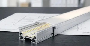
To inspect physical joints and mounting, check every solder joint and connector for secure contact, look for gaps or overlaps between strip sections, verify that mounting clips and adhesive remain firmly attached along the full length, and confirm that no strip section has sagged, shifted, or pulled away from its channel. Address any looseness immediately to prevent visible light breaks.
Why Joints Fail
In long-run installations, thermal expansion and contraction 8 cause strips to shift slightly over time. Vibration from nearby machinery, wind loading on outdoor facades, and even building settlement can stress connection points. Solder joints crack. Snap connectors loosen. Adhesive tape loses its grip. Each of these creates a potential point of light discontinuity or complete electrical failure.
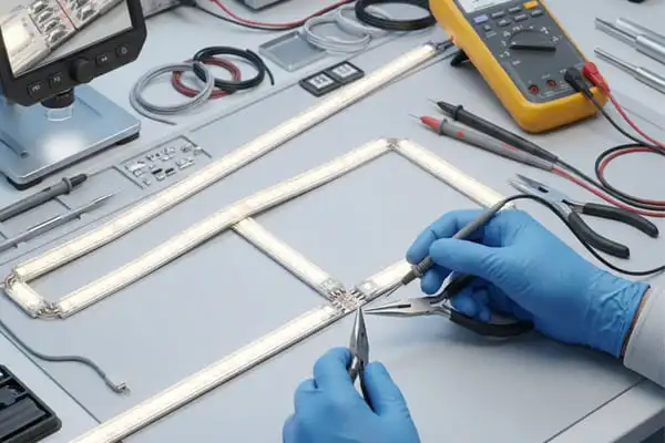
Joint-by-Joint Inspection
Walk the full length of every run. At each joint:
- Gently press each connector to confirm it is seated firmly.
- Look for any visible gap between adjacent strip sections.
- Check solder joints (if accessible) for cracks, cold solder, or discoloration.
- Verify that the wiring at each joint is not under tension or being pulled.
If a connector wiggles or a solder joint looks dull and cracked, mark it for rework.
Mounting and Adhesive Check
Strip adhesive is designed for one-time application. Once it peels, reapplying it rarely works as well. In our production, we always recommend aluminum channels with mechanical clips for industrial projects. But regardless of the mounting method, you need to inspect:
- Is the strip sitting flat against the mounting surface along its full length?
- Are there any sections where the strip has sagged away from the surface?
- Are mounting clips still tight?
- Has the aluminum channel shifted or loosened from its brackets?
Common Mounting Failures and Solutions
| Failure Type | Typical Cause | Recommended Fix |
|---|---|---|
| Adhesive peeling | Heat, dust on surface, wrong tape type | Clean surface, use aluminum channel with clips |
| Strip sagging | Gravity on vertical or overhead runs | Add mounting clips at closer intervals |
| Channel loosened | Vibration or thermal movement | Re-secure brackets; add lock washers |
| Connector gap | Thermal expansion pulled sections apart | Use flexible jumper wires between sections |
| Solder joint crack | Repeated thermal cycling | Re-solder or replace connector |
Preventing Light Discontinuity
The best defense is proper installation design. When we work with contractors on long-run projects, we always recommend flexible bridge connectors at every junction, mechanical mounting instead of adhesive alone, and expansion gaps planned into the layout. During inspection, if you see that the original installation did not account for these factors, document the risk and plan for retrofits before failures become visible to the end user.
What electrical and thermal indicators should I monitor to ensure my industrial lighting system remains stable?
Electrical and thermal failures do not usually announce themselves loudly. They start as small anomalies: a slightly warm connector, a faint flicker, a minor voltage drop 9. If you know what to monitor, you can catch these early.
Monitor input voltage at the power supply and at the far end of each strip run, measure current draw against rated specifications, use an infrared thermometer to check for hotspots at connectors and driver housings, and look for signs of scorching, melted insulation, or discolored PCB traces. Any deviation from baseline readings indicates a developing problem that needs immediate attention.

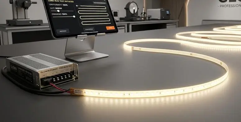
Voltage Drop: The Silent Killer
Voltage drop over long runs is one of the most common issues in industrial LED strip installations. The further electricity travels along the copper traces, the more voltage it loses. If the voltage at the far end of a run drops below the LED's operating threshold, you get dimming, flickering, or complete failure of the last section. During inspection, measure voltage at both the power supply output and the far end of the longest run. The difference tells you how much drop you have.
What to Measure and How Often
| Parameter | Tool | Baseline Check | Warning Threshold |
|---|---|---|---|
| Supply output voltage | Multimeter | At commissioning | ±5% of rated output |
| End-of-run voltage | Multimeter | At commissioning | More than 1V drop from supply |
| Current draw per run | Clamp meter | At commissioning | More than 10% above rated load |
| Connector temperature | IR thermometer | At commissioning | More than 20°C above ambient |
| Driver housing temperature | IR thermometer | At commissioning | More than 60°C surface temp |
| Power consumption (total) | Energy meter | Monthly | More than 15% increase from baseline |
Recognizing Thermal Warning Signs
Heat is the enemy of LED longevity. During your inspection, use an infrared thermometer 10 or thermal camera to scan the full length of the installation. Pay special attention to:
- Connector joints (where resistance builds up and generates heat)
- Power supply and driver housings
- Sections where the strip runs through enclosed spaces without ventilation
- Any point where you see discoloration, browning, or warping of the strip or its channel
In our testing lab, we have seen connectors reach over 80°C when they are not properly crimped. That kind of heat degrades the connector, the strip, and the insulation around it. It also creates a fire risk. If any point is noticeably hotter than the surrounding area, investigate immediately.
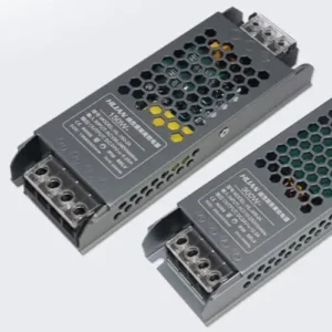
Power Supply Health
The power supply is the heart of the system. Check for:
- Unusual buzzing or humming sounds
- Burning smell
- Swollen or leaking capacitors (if the housing is transparent or vented)
- Output voltage stability under load
A power supply that is overloaded will run hot and fail early. Make sure the total connected load does not exceed 80% of the supply's rated capacity. This gives headroom for startup surges and ambient heat.
Documenting Your Findings
Every inspection should produce a written record. Include the date, location, asset ID, measurements taken, any defects found, and what corrective action was taken or planned. Over time, this documentation reveals patterns. Maybe a particular connector type fails frequently. Maybe a certain installation zone always runs hot. These patterns help you make smarter purchasing and installation decisions for future projects.
Energy Consumption Tracking
One often-overlooked indicator is total energy consumption. If your LED strip system starts drawing significantly more power than it did at commissioning, something has changed. It could be a failing driver compensating for degraded LEDs, a short developing somewhere in the circuit, or an additional load that was connected without updating the design. Compare current energy readings against your baseline data at least quarterly.
Conclusion
A thorough inspection checklist is a preventive tool, not just a formality. Check seals, color, joints, voltage, and temperature regularly, and document every finding to keep your industrial LED strip systems safe and reliable.
Footnotes
- Explains the IEC IP code system for protection against solids and liquids. ↩︎
- Details how UV radiation causes photodegradation in polymers, affecting physical properties. ↩︎
- Explains the significance of UL labels for product safety and compliance. ↩︎
- Defines LED color shift and discusses its causes and impact on lighting projects. ↩︎
- Located an authoritative .gov source discussing irreversible phosphor degradation as a cause of chromaticity shifts in LED devices. ↩︎
- Describes what a lux meter is and its function in measuring illuminance. ↩︎
- Defines Correlated Color Temperature (CCT) and its measurement in Kelvin for white light. ↩︎
- Replaced with an authoritative source (Britannica) providing a general increase in the volume of a material as its temperature is increased, which implicitly covers contraction. ↩︎
- Describes voltage drop as the reduction in electrical potential due to resistance in conductors. ↩︎
- Explains the working principle of infrared thermometers using thermal radiation. ↩︎