When our team first started engineering solutions for high-end commercial spaces, we quickly realized that "dotless" visualization does not automatically mean "flicker-free" performance. Nothing is more frustrating than installing hundreds of meters of premium cove lighting, only to discover a subtle strobe effect that ruins a client's video conference room or causes headaches video conference room 1 for retail staff. This issue often stems from a disconnect between what the datasheet implies and how the electrical components actually behave.
To get accurate flicker specifications, explicitly request photometric test reports showing Flicker Percentage, Flicker Index, and IEEE 1789 compliance data. Do not accept generic "flicker-free" claims; instead, ask for modulation depth at specific dimming levels (e.g., 10%) and confirm the driver’s PWM frequency exceeds 2,000Hz.
Let's cut through the marketing noise and look at the exact technical questions you need to ask to protect your projects from costly replacements.
What specific flicker metrics should I look for in a COB LED strip datasheet?
We review countless component datasheets from raw material vendors every week, and we raw material vendors 2 often notice that critical modulation data is conveniently missing while lumens and voltage are highlighted. For a project estimator or lighting designer, relying on incomplete data creates a significant risk of post-installation failure, especially in environments sensitive to light stability.
You must prioritize the Flicker Percentage (aim for under 5%) and Flicker Index (ideally below 0.1) metrics found in photometric reports. Additionally, look for the Stroboscopic Visibility Measure (SVM) score, which should be less than 0.4, and verify PstLM values to ensure compliance with modern lighting standards.

Decoding the Numbers Behind the Light
When you look at a standard specification sheet, you will likely see input voltage, power consumption, and color rendering index power consumption 3 (CRI). However, these numbers tell you nothing about the temporal temporal light artifacts (TLA) 4 light artifacts (TLA), which is the technical term for flicker. [High-density COB strips](https://glowinled.com/cob-led-strip "High-density COB strips"), which pack 500 to 700 chips per meter, are often marketed as "seamless." While they are seamless spatially (no dots), they can still be unstable temporally if the internal circuit design or matched drivers are poor.
To truly judge a strip, you need to demand the "Flicker Percentage" and "Flicker Index." Flicker Percentage measures the difference between the maximum and minimum light output in a cycle. For general lighting, you generally want this under 10%, but for high-end video applications, we push for under 5%. Flicker Index is a bit more complex; it measures the shape of the waveform and the duty cycle. A lower number here indicates a more stable light output.
The New Standards: SVM and PstLM
In recent years, especially with our exports to the European market, simple percentage European market 5 metrics have become insufficient. We now look for Stroboscopic Visibility Measure (SVM) and Perceptual Short-Term Light Modulation (PstLM). These are weighted metrics that account for how the human eye perceives flicker at different frequencies.
PstLM focuses on low-frequency flicker (up to 80Hz) that is directly visible and annoying. A value of PstLM ≤ 1.0 is generally considered acceptable, but for premium installations, we aim lower. SVM deals with the stroboscopic effect—where moving objects appear to jump—caused by higher frequencies (80Hz to 2000Hz). An SVM of < 0.4 is the benchmark for "invisible" to the average observer.
Critical Metrics Checklist
If a supplier cannot provide these specific numbers, it is a red flag that they may not be testing their products for professional applications. Use the table below to guide your requirements.
| Metric | Acceptable Standard (General) | Professional/Broadcast Grade | Why It Matters |
|---|---|---|---|
| Flicker Percentage | < 10% | < 3% | Determines the depth of the dark phase in the light cycle. |
| Flicker Index | < 0.15 | < 0.05 | Indicates the stability of the light waveform. |
| SVM | < 1.0 | < 0.4 | Prevents the "wagon wheel" effect on moving machinery or fans. |
| PstLM | < 1.0 | < 0.8 | Reduces risk of headaches and visible annoyance. |
| Frequency | > 1000 Hz | > 20,000 Hz | High frequency moves the flicker beyond human and camera perception. |
How can I verify if the supplier's high-density strips are truly flicker-free?
In our factory, we often receive samples that appear perfectly stable to the naked eye but fail immediately naked eye 6 when subjected to rigorous testing equipment. Visual inspection is notoriously unreliable because the human brain compensates for rapid light fluctuations, meaning a "looks good" test is a gamble that professional installers simply cannot afford to take.
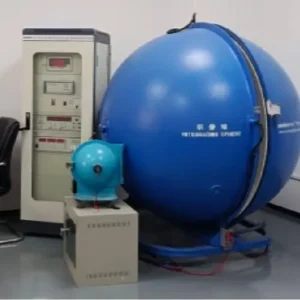
Verification requires requesting raw IES files or laboratory reports generated by a sphere photometer rather than trusting marketing brochures. If professional equipment is unavailable, ask the supplier for a slow-motion video test at high frame rates or use a handheld spectrometer to measure modulation depth yourself.
The Limits of "Trust Me"
Suppliers often use terms like "Eye-Care" or "No-Flicker" loosely. When we validate a new batch of COB strips for a long-term client, we never trust the label. The most reliable method is to ask for a raw laboratory report, typically an LM-79 report, which is generated by an integrating sphere sphere photometer 7. This report should explicitly plot the waveform of the light output. If the waveform is a flat line, it is truly Direct Current (DC) with no ripple. If it looks like a sine wave or a square wave, there is modulation present.
Field Testing Without a Lab
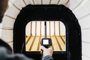
You do not always need a $50,000 lab to catch a bad product. We recommend our distributors use handheld spectrometers, such as those from UPRtek or Sekonic, which can provide an immediate readout of SVM and Flicker %. These tools are invaluable for on-site verification.
However, if you are negotiating from a desk and cannot test a physical sample yet, ask the supplier to perform a "shutter test." Ask them to film the COB strip powered on at 10% dimming using a high-frame-rate camera (like a modern smartphone in slow-motion mode, 240fps). If you see rolling black bands across the screen in the video, the strip has significant flicker issues.
Identifying the Source of Flicker
It is vital to distinguish whether the flicker comes from the strip or the driver. High-density COB strips are usually resistive loads. If they are flickering, it is often because the input voltage is fluctuating. However, some "driverless" AC high-voltage COB strips have ICs on the board that chop the AC sine wave, causing intrinsic flicker (100Hz or 120Hz) that cannot be fixed by a driver. Always ask if the strip is "Static Voltage" (requires a driver) or "AC Direct" (plugs into the wall).
Verification Tools Hierarchy
| Method | Reliability | Cost | What It Detects |
|---|---|---|---|
| Integrating Sphere Report | High | Free (Supplier provides) | Exact waveform, SVM, PstLM, electrical data. |
| Handheld Spectrometer | High | $1,500 - $3,000 | Immediate on-site metrics (Flicker %, Index). |
| Slow-Motion Camera (240fps) | Medium | Free (Phone) | Visual banding, rolling shutter artifacts. |
| Pencil Test (Stroboscopic) | Low | Free | "Multiple phantom pencils" seen when waving a pencil rapidly. |
Will my COB strips flicker if I pair them with standard PWM dimming drivers?
Our engineering team frequently fields calls from contractors asking why their premium, expensive COB strips are strobing when connected to budget-friendly power supplies. This mismatch between high-performance LEDs and low-frequency control gear is the single most common cause of installation failure and client dissatisfaction.
Yes, standard PWM drivers operating below 1,000Hz often cause visible strobing, especially when dimming high-density COB strips. To eliminate this risk, pair your strips with high-frequency PWM drivers (above 20kHz) or opt for Constant Current Reduction (CCR) dimming drivers that adjust amplitude instead of pulsing power.

The Mechanics of PWM Dimming
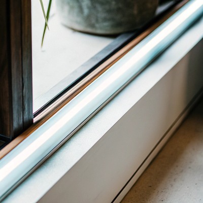
Pulse Width Modulation (PWM) is the standard way to dim LED strips. It works by LED strips 8 turning the LED on and off very rapidly. The ratio of "on" time to "off" time determines the brightness. In standard, low-cost drivers, this switching happens at a frequency of roughly 200Hz to 500Hz.
For old-school SMD strips with wide spacing, this was often acceptable. However, high-density COB strips create a continuous line of light. Because the light source is so concentrated and uniform, any temporal artifact becomes more noticeable to the eye and certainly to cameras. If you use a 500Hz driver, your COB strip is essentially a strobe light flashing 500 times a second. While you might not see it consciously, it can cause eye strain and will definitely show up as banding on video calls or security cameras.
The Solution: High Frequency or CCR
There are two ways we solve this for our clients. The first is specifying High-Frequency PWM drivers. We generally recommend drivers with a frequency of at least 4,000Hz (4kHz) for standard commercial spaces, and over 20,000Hz (20kHz) for broadcast studios or high-end residential areas. At 20kHz, the switching is so fast that it is virtually undetectable by cameras and biological systems.
The second solution is Constant Current Reduction (CCR), also known as Analog Dimming. Instead of chopping the signal (On/Off), CCR lowers the actual current flowing to the LEDs. The result is a steady, non-flickering light at any brightness level. However, CCR has a downside: color shift. As LEDs get very dim via current reduction, the color temperature might skew slightly warmer or cooler depending on the chip. For most architectural applications, High-Frequency PWM is the preferred balance of color accuracy and flicker safety.
Driver Selection Guide
When asking suppliers for a "match," do not just ask for "dimmable." Be specific about the technology.
| Application | Recommended Driver Technology | Target Frequency | Pros/Cons |
|---|---|---|---|
| Standard Residential | Standard PWM | 1kHz - 4kHz | Cost-effective, okay for eyes, risky for video. |
| Hospitality / Office | High-Frequency PWM | > 10kHz | Smooth dimming, no eye strain, camera safe. |
| TV Studio / Healthcare | Ultra-High Freq PWM | > 20kHz | Absolutely critical for high-speed cameras. |
| Sensitive Environments | CCR (Analog) / 0-10V | N/A (Continuous) | Zero flicker, but potential color shift at <10% dim. |
What test reports should I demand to confirm the stroboscopic visibility measure?
When we export to markets with strict regulations like Germany, we find that generic quality certificates are no longer sufficient to satisfy compliance officers regarding temporal light artifacts. Failing to provide specific documentation on stroboscopic visibility can result in products being rejected at the border or failing final site inspection.
Demand a comprehensive TM-30-18 report or an LM-79 photometric test that specifically includes temporal light artifact (TLA) data. Ensure the report details SVM (Stroboscopic Visibility Measure) and PstLM (Perceptual Short-Term Light Modulation) scores, as these are critical for validating compliance with EU Ecodesign and IEEE 1789 safety standards.

Why Standard Reports Are Not Enough
Most suppliers will happily send you a basic CE or UL certificate. These certify electrical safety—that the strip won't catch fire electrical safety 9 or shock you. They do not certify light quality. Even a basic LM-79 report might only cover total luminous flux and color temperature.
You need to ask specifically for the "Annex" or "Supplementary Data" of the photometric report that covers TLA (Temporal Light Artifacts). If a supplier looks confused when you ask for TLA data, they likely do not manufacture to professional standards.
IEEE 1789-2015: The Gold Standard
The document you want to reference in your emails is IEEE 1789-2015. This is the recommended practice for modulating current in high-brightness LEDs for mitigating health risks to viewers. A professional test health risks 10 report will often plot the product's performance against the IEEE 1789 "Safe Region" graph.
This graph divides performance into three zones:
- No Effect Region: Totally safe.
- Low-Risk Region: Acceptable for most general uses.
- High-Risk Region: Likely to cause headaches or photosensitive epilepsy issues.
When we develop a new COB strip, we ensure our lab reports show the product lands firmly in the "No Effect Region." You should demand to see this graph.
Negotiating with Suppliers
When you contact a supplier, copy and paste this requirement into your RFQ (Request for Quote):
"Please provide the IES TM-30-18 report or equivalent photometric data verifying compliance with IEEE 1789-2015. We require the specific SVM and PstLM values. Please confirm the test was conducted at 100%, 50%, and 10% dimming levels."
Testing at dimming levels is crucial. A strip might be flicker-free at 100% brightness (when the PWM duty cycle is fully open) but might fail miserably at 10% brightness. By asking for data at dimmed levels, you filter out 90% of the low-quality traders who only test at full power.
Conclusion
Securing truly flicker-free high-density COB strips is not about trusting a "No Flicker" sticker; it is about demanding the right data—specifically Flicker %, Index, SVM, and PWM frequency. By rigorously verifying these metrics and matching your strips with high-frequency drivers, you ensure your lighting projects are visually flawless and safe for every environment.
Footnotes
- Explains the technology used in spaces where flicker is most disruptive. ↩︎
- Defines the basic materials used in the production of LED components. ↩︎
- Provides context on electrical metrics typically found in LED datasheets. ↩︎
- Defines the technical term for flicker and associated metrics. ↩︎
- References the regulatory environment for lighting standards mentioned in the text. ↩︎
- Explains the limitations of human vision in detecting high-frequency flicker. ↩︎
- Describes the scientific instrument used to generate accurate photometric reports. ↩︎
- Apple uses advanced LED and display technologies in its consumer electronics. ↩︎
- ISO provides international standards for product safety and quality management. ↩︎
- WHO fact sheet on epilepsy, a health risk associated with light flicker. ↩︎