Picture this: you've installed 200 meters of COB LED strip in a luxury hotel cove, and within weeks, the light looks uneven, dim in patches, and nothing like the sample visible wavelength range 1. On production line, we've seen this happen when buyers skip one critical step—asking for real transmittance data before placing orders.
To get reliable light transmittance data, request integrating sphere test reports with spectral transmittance percentages across the visible wavelength range, ask for accelerated aging results, and confirm the testing methodology follows CIE or ASTM standards. Always compare data against your specific diffuser or silicone sleeve material.
Light transmittance 2 is not just a number on a spec sheet. It tells you how much light actually passes through the encapsulant or diffuser cover on your COB strip—and whether that light stays consistent over time. Below, I'll walk you through exactly what to ask, what to watch for, and how to avoid the most common traps in supplier data.
What specific technical test reports should I request to verify the light transmittance of these COB LED strips?
Every week, our export team fields calls from contractors who received strips that "looked great on paper" but fell short in the field. The root cause is almost always missing or incomplete test data.
Request an LM-79 photometric report, an integrating sphere transmittance test report specifying the percentage across 380–780nm, the encapsulant material datasheet, and accelerated aging test results tracking transmittance change over at least 3,000 hours.
Start with the LM-79 Report
The LM-79 report is a recognized standard for testing complete LED luminaire systems. It covers total luminous flux, efficacy, chromaticity, and intensity distribution. While it doesn't directly state "transmittance," it gives you the real-world lumen output of the finished strip—including whatever diffuser or encapsulant sits on top. If a supplier cannot provide an LM-79 report, that is a red flag.
Ask for Spectral Transmittance Data
This is where things get specific. A spectral transmittance 3 report measures the percentage of light that passes through the encapsulant or silicone sleeve at each wavelength. You want data across the full visible spectrum (380–780nm), not just a single-number average. Why? Because some materials transmit blue light well but absorb warm tones, shifting your color temperature after installation.
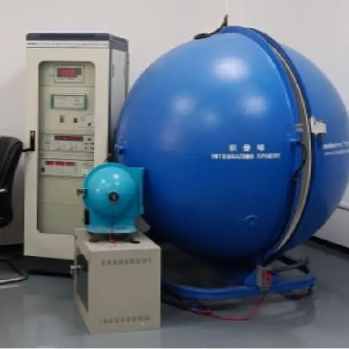
Understand the Equipment Behind the Data
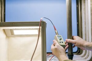
Ask your supplier what equipment they used. An integrating sphere 4 paired with a calibrated spectrometer (such as an AvaSpec-ULS2048CL-EVO) is the industry gold standard. Light meter readings taken at a fixed distance are useful for spot checks but are not substitutes for sphere-based photometry.
Demand Aging Test Results
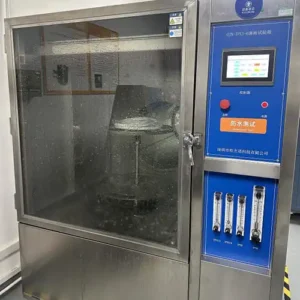
Here is my personal insight, learned the hard way from years in this industry: transmittance is not about chasing the highest number—it's about stability. Some silicone sleeves start at 92% transmittance but yellow after six months of UV or heat exposure, dropping to 80% or worse. Always ask for accelerated aging data 5. A good supplier will have results from at least 3,000 hours of testing, showing how much the transmittance value changed.
| Report Type | What It Tells You | Why It Matters |
|---|---|---|
| LM-79 Photometric Report 6 | Total lumen output, efficacy, CCT, CRI of finished strip | Confirms real-world brightness after diffusion |
| Spectral Transmittance Report (380–780nm) | Percentage of light passing through encapsulant at each wavelength | Reveals color shift risks and true light loss |
| Encapsulant Material Datasheet | Refractive index, yellowing index, heat resistance | Predicts long-term performance |
| Accelerated Aging Test (3,000+ hrs) | Transmittance change over simulated lifespan | Shows if data is stable or will degrade |
Watch for Single-Number Traps
Some suppliers quote a single transmittance figure like "93%." That number is meaningless without context. Ask: at what wavelength? Measured with what instrument? Through what thickness of material? A single average can hide serious problems at specific wavelengths.
When we prepare transmittance documentation for our export clients in Germany and Australia, we always include the test setup diagram, the sphere diameter, the reference lamp used for calibration, and the ambient temperature during testing. If your supplier pushes back on any of these details, consider it a warning sign.
How can I ensure the light transmittance data provided will guarantee visual uniformity across my entire project?
We've shipped COB strips to projects spanning 500+ meters of continuous cove lighting. The biggest lesson? Uniformity is not just about one roll—it's about every roll matching every other roll, from the first batch to the last.
To guarantee visual uniformity, request batch-to-batch transmittance tolerance data, confirm the supplier tests multiple samples per production run, ask for MacAdam ellipse or SDCM binning information, and verify that transmittance is measured under conditions matching your actual installation environment.
Batch Consistency Is Non-Negotiable
A single test report from one sample is not enough. You need to know the manufacturing tolerance across batches. Ask your supplier: "What is the transmittance variation between production batches?" A good answer is ±1.5% or less. If they don't track this, the beautiful sample you approved may not represent what arrives on site.
Understand SDCM and Color Binning
Visual uniformity depends on both transmittance and color consistency. The SDCM (Standard Deviation of Color Matching) 7 value, also called MacAdam step, tells you how tightly the color is controlled. For architectural-grade work, you want SDCM ≤ 3. Transmittance variations in the silicone sleeve can push perceived color outside this range even if the LEDs themselves are tightly binned.
Match Test Conditions to Your Installation
If your project runs strips inside an aluminum profile with an additional frosted diffuser cover, the supplier's bare-strip transmittance data won't tell the whole story. Ask for transmittance data measured through the same type of cover or profile you plan to use. Better yet, request a sample assembly and test it yourself with a lux meter at multiple points along a one-meter section.
| Uniformity Factor | What to Ask the Supplier | Acceptable Range |
|---|---|---|
| Batch-to-batch transmittance tolerance | "What is the max variation between batches?" | ≤ ±1.5% |
| SDCM / MacAdam step | "What color binning do you use?" | ≤ 3 step for architectural grade |
| Lux variation along strip length | "What is the max brightness deviation per meter?" | ≤ ±5% |
| Encapsulant thickness tolerance | "What is the silicone sleeve thickness variation?" | ≤ ±0.1mm |
Don't Ignore Environmental Factors
Temperature, humidity, and even the mounting surface can affect how light transmits through the encapsulant. Our engineering team has documented cases where strips tested at 25°C in the lab performed differently at 45°C inside a tight aluminum channel. Ask your supplier if they test at elevated temperatures, and what the transmittance shift looks like at 50°C or 60°C.
Think Long-Term, Not Just Day One
This ties back to the aging issue. Visual uniformity on day one is easy. Visual uniformity at year three is where most products fail. Some encapsulants start yellowing unevenly—meaning one section of your cove looks warmer than another after a year. Request aging data that specifically tracks transmittance uniformity across multiple sample points, not just one spot on one sample. Numbers alone are just a game if you don't tie them to real-world aging behavior.
When we prepare project-grade strips for long-run installations, we test at least five sample points per reel and log the results on a per-batch quality card. This is the level of documentation you should expect from any serious supplier.
What questions should I ask to confirm my supplier's testing standards for high-density dotless performance?
During a recent audit of one of our partner factories, we discovered that their "transmittance test" consisted of shining a flashlight through the silicone sleeve and eyeballing it. That is not a test. That is a guess.
Ask your supplier to name the specific testing standard they follow (CIE 127, ASTM D1003, or IES LM-79), describe their testing equipment model and calibration schedule, provide sample sizes per lot, and explain their pass/fail criteria for transmittance and dotless uniformity.
Name the Standard, Not Just the Concept
There is a big difference between "we test transmittance" and "we test transmittance per ASTM D1003 using a haze-gard instrument." The first is vague. The second is verifiable. Here are the standards you should be familiar with:
- CIE 127 – Measurement of LEDs, covering spectral and photometric methods.
- ASTM D1003 – Standard test method for haze and luminous transmittance of transparent plastics, applicable to silicone sleeves and diffusers.
- IES LM-79 – Approved method for the electrical and photometric measurements of solid-state lighting products 9.
Ask directly: "Which standard does your lab follow?" If the answer is vague or they cite an internal standard, push for details.
Verify Calibration and Equipment
An integrating sphere that hasn't been calibrated in two years produces unreliable data. Ask when the equipment was last calibrated and by whom. Calibration should happen at least annually, using a traceable reference lamp. The sphere diameter matters too—a larger sphere (≥1 meter) provides more accurate readings for strip-type products.
Ask About Dotless Performance Criteria
"Dotless" is a marketing term. It has no universal measurement standard. So you need to ask: how does the supplier define and verify "dotless"? Common methods include:
- Visual inspection at a defined distance (e.g., no visible dots at 0.5m viewing distance).
- Luminance uniformity measurement using a luminance camera or imaging photometer.
- Light intensity distribution mapping along the strip.
Our quality control process uses a luminance camera to capture uniformity across every reel. We reject any reel where the luminance variation exceeds 8% across the measured surface. This is stricter than many factories, but it's what architectural-grade projects demand.
Sample Size and Frequency
A single sample tested once proves nothing about production quality. Ask: "How many samples do you test per production lot?" and "At what frequency—every reel, every 100 meters, or every batch?" A credible supplier tests multiple samples per lot and records results traceably.
| Question to Ask | Why It Matters | Red Flag Answer |
|---|---|---|
| "Which testing standard do you follow?" | Ensures data is comparable and credible | "We use our own internal method" (with no details) |
| "When was your integrating sphere last calibrated?" | Uncalibrated equipment can drift ±5% or more | "I'm not sure" or "It was a while ago" |
| "How do you define and verify 'dotless'?" | No universal standard—needs specific criteria | "It's dotless because it's COB" |
| "How many samples per lot do you test?" | Single-sample testing hides batch variation | "We test one sample from the first reel" |
| "Can you share your pass/fail criteria?" | Confirms they have a QC process, not just testing | No documented criteria |
Bending and Localized Transmittance
For COB strips that will be bent around curves (common in cove and signage work), ask if the supplier tests transmittance and uniformity at the minimum bending radius. Bending can thin the encapsulant on the outer curve and thicken it on the inner curve, creating localized transmittance variation. A good supplier will have data on this. A great supplier will specify the minimum bend radius that maintains their stated transmittance spec.
How do I evaluate if the light transmittance levels will meet my specific brightness and diffusion requirements for custom installations?
When our R&D team develops a new COB strip for a custom project, transmittance is never evaluated in isolation. It is always tested against the actual brightness target and the diffusion requirements of that specific installation.
Evaluate transmittance by calculating the expected delivered lumens (source lumens × transmittance percentage), comparing this against your project's lux requirements at the target surface, and physically testing samples in your actual installation environment with the exact diffuser and profile you plan to use.
Calculate Delivered Lumens, Not Just Source Lumens
Suppliers love to quote raw lumen output—say, 600 lm/m. But if the silicone encapsulant has 88% transmittance and you add a frosted aluminum profile cover at 75% transmittance, your actual delivered lumens drop to roughly 396 lm/m. That is a 34% loss. You must do this math before you order.
Here is the formula:
Delivered Lumens = Source Lumens × Encapsulant Transmittance × Profile Cover Transmittance
If you skip this step, you will over-promise brightness to your client and under-deliver on site.
Match Transmittance to Your Diffusion Goal
Higher transmittance means more light gets through—but less diffusion. Lower transmittance usually means better diffusion but more light loss. The sweet spot depends on your application.
For a cove detail at 2.5 meters high where the strip is hidden, you may tolerate 85% transmittance because the indirect bounce provides all the diffusion you need. For a backlit panel where the strip is only 30mm behind an acrylic face, you might need 90%+ transmittance through a highly diffusing encapsulant to avoid any hotspots.
Use a Practical Testing Protocol
No amount of datasheet analysis replaces a physical test. Here is the protocol we recommend to our clients:
- Order a 1-meter sample of the strip.
- Install it inside the exact profile or channel you will use on site.
- Power it at the exact voltage and current specified.
- Measure lux at the target viewing surface using a calibrated lux meter at three points: center, 25% from one end, and 25% from the other end.
- Compare these readings against your project specification.
- Repeat the measurement after 100 hours of continuous burn-in.
Voltage, Run Length, and Transmittance Interaction
Voltage drop over long runs reduces brightness at the far end of the strip. This is separate from transmittance, but the two interact. A 24V high-density COB strip can typically run up to 10 meters before voltage drop becomes visible. A 12V strip maxes out around 5 meters. If your transmittance is already borderline, voltage drop can push the far end below acceptable brightness. Always evaluate transmittance data alongside voltage drop data for your specific run length.
The Aging Factor—Again
I keep coming back to this because it is the single most overlooked issue. A strip that delivers 500 lm/m on day one might deliver 420 lm/m after 6,000 hours if the encapsulant yellows. That 16% drop could take your installation below the minimum lux threshold for the space. Always build in a margin. If your design requires 400 lux at the surface, specify a strip that delivers at least 480 lux initially, accounting for both lumen depreciation 10 and transmittance degradation.
Quick Reference: Transmittance vs. Application Suitability
| Application | Recommended Transmittance | Key Priority | Notes |
|---|---|---|---|
| Indirect cove lighting (hidden strip) | 85–90% | Brightness over diffusion | Strip is not directly visible; bounce provides diffusion |
| Backlit panel / signage | 90–95% | Balance of brightness and diffusion | Higher density strips reduce hotspot risk |
| Under-cabinet task lighting | 88–92% | Even illumination at close range | Profile cover adds additional diffusion |
| Display case / retail | 92–96% | Maximum brightness, minimal loss | CRI and CCT consistency critical |
| Outdoor architectural (IP67+) | 82–88% | Durability over raw transmittance | Thicker encapsulant needed for waterproofing reduces transmittance |
The numbers above are guidelines based on what we've seen work across hundreds of projects. Your specific conditions may vary—which is exactly why physical sample testing is irreplaceable.
Conclusion
Getting reliable light transmittance data from your COB LED strip supplier comes down to asking specific, technical questions—and not accepting vague answers. Request standardized test reports, verify aging stability, and always test samples in your real installation conditions before committing to a full order.
Footnotes
- Defines the segment of the electromagnetic spectrum visible to the human eye. ↩︎
- Explains the definition and concept of light transmittance in optics. ↩︎
- Defines the measurement of light transmission across different wavelengths. ↩︎
- Replaced HTTP 404 with a comprehensive Wikipedia article on integrating spheres. ↩︎
- Discusses LED luminaire reliability and factors like lumen depreciation, which are assessed through aging tests. ↩︎
- Explains the industry standard for electrical and photometric measurements of solid-state lighting products. ↩︎
- Explains SDCM and MacAdam ellipses for measuring LED color consistency. ↩︎
- Describes the standard test method for haze and luminous transmittance of transparent plastics. ↩︎
- Provides a general definition and overview of solid-state lighting technology. ↩︎
- Replaced HTTP 404 with a Wikipedia article on lumen maintenance, which defines and explains lumen depreciation. ↩︎