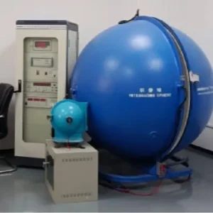
I often see clients frustrated when their carefully designed 20-meter light runs fade visibly at the far end, ruining the visual consistency of a high-end lobby or exterior facade. We test every batch in our aging room, and we know that simply asking for "dual-ended power" isn't enough to guarantee uniform brightness; you need to understand the underlying physics of the strip itself.
To effectively inquire about dual-ended power supply, specify your total run length, voltage preference (24V or 48V), and dimming requirements. Ask suppliers for voltage drop data at both ends voltage drop 2 and confirm if the strip's internal copper thickness supports the current load required for dual injection without overheating.
Let’s break down the technical details you need to discuss with your supplier to ensure a flawless installation and avoid common pitfalls.
Will dual-ended power feeding eliminate voltage drop in my long LED runs?
It is disappointing to install premium lighting only to see the far end looking dimmer than the start, creating an unprofessional gradient effect. When we engineer custom PCBs for large-scale commercial projects, we often remind clients that feeding power from both ends is a helpful technique, but it is not a magic wand for poor circuit design.
Dual-ended power feeding significantly reduces visible [voltage drop](https://glowinled.com/how-to-evaluate-voltage-drop-in-led-strips-after-prolonged-use/ "voltage drop") but does not completely eliminate it. It equalizes voltage distribution, ensuring the middle section remains bright. However, without sufficient copper thickness on the PCB, resistance will still cause dimming or overheating, even with power injected at both ends.
The Science Behind the Voltage Drop
When you ask a supplier about dual-ended power, you are essentially asking about current distribution. In a standard single-end feed, the voltage is highest at the injection point and drops progressively as it travels down the copper traces of the Flexible Printed Circuit (FPC) Flexible Printed Circuit 3. By the time the current reaches the LEDs at the end of a long run, the voltage may be insufficient to drive them at full brightness.
Dual-ended feeding (injecting power at both the head and tail of the strip) attacks this problem from two sides. Ideally, the voltage meets in the middle. However, the success of this method depends entirely on the internal structure of the LED strip, specifically the copper weight.
Why Copper Weight Matters More Than Wiring
Many buyers assume that connecting wires to both ends solves the problem. It does not. If the FPC is too thin—say, using 1 ounce (oz) of rolled copper instead of 2oz or 3oz—the internal resistance remains high internal resistance 4.
When we design strips for long runs, we increase the [copper thickness](https://glowinled.com/how-to-verify-copper-thickness-standards-in-high-density-dotless-cob-led-strips/ "copper thickness"). If you force current into both ends of a thin strip, you might get better uniformity, but you also risk heating up the FPC because the "road" (copper trace) is too narrow for the "traffic" (current). This heat degrades the LED chips and the adhesive backing over time. Therefore, your inquiry must go beyond "Can I feed both ends?" to "Is the PCB designed to handle the current of a dual-feed setup?"
Voltage Drop Comparison Data
We simulated the performance of a standard 24V LED strip versus a high-copper version to illustrate why the strip quality dictates the success of dual-feeding.
| Power Feed Method | PCB Copper Weight | Voltage at Start (0m) | Voltage at Middle (5m) | Voltage at End (10m) | Visual Result |
|---|---|---|---|---|---|
| Single-Ended | 1 oz (Standard) | 24.0V | 22.1V | 20.5V | Visible dimming at the end. |
| Single-Ended | 3 oz (Premium) | 24.0V | 23.2V | 22.4V | Slight dimming, barely visible. |
| Dual-Ended | 1 oz (Standard) | 24.0V | 22.5V (Lowest Point) | 24.0V | Center is dimmer; strip runs hot. |
| Dual-Ended | 3 oz (Premium) | 24.0V | 23.6V (Lowest Point) | 24.0V | Perfectly uniform brightness. |
As shown in the table, dual-ended feeding on a premium PCB yields the best result. When inquiring, ask your supplier for this specific data: "What is the voltage at the center point of the run when powered from both ends?" If they cannot answer, they may not have tested it.
Can I request pre-soldered wires on both ends to speed up on-site installation?
Field soldering is a nightmare for contractors, especially when working on ladders or in damp outdoor conditions where moisture compromises the joint. We frequently customize orders by adding factory-sealed leads to our reels, saving installation teams hours of labor and preventing failures caused by cold solder joints or weak connections.
Yes, requesting pre-soldered wires on both ends is a standard industry practice that reduces labor costs and improves reliability. Factory-soldered connections are typically machine-applied and heat-shrink sealed, offering superior water resistance and tensile strength compared to tensile strength 5 manual soldering performed at the installation site.

Factory Precision vs. Field Risk
In our production facility, soldering is not just about making an electrical connection; it is about mechanical stability. When you inquire about dual-ended power, you should explicitly request "factory-soldered fly leads" on both ends of the reel.
Manual soldering on-site is prone to error. An installer balancing on a scaffold may not apply enough heat, resulting in a "cold joint" that creates resistance and eventually sparks or fails. Furthermore, resealing a waterproof [IP67 or IP68 strip ](https://glowinled.com/ip67-vs-ip68-led-strip-waterproof-guide/ "IP67 or IP68 strip ")on-site IP67 or IP68 6 is difficult. Once you cut the silicone sleeve to solder, it is hard to restore the original waterproof integrity.
Customizing the Lead Length
A crucial part of your inquiry involves the length of these pre-soldered wires. Standard factory leads are often short (around 15-20cm). For a dual-feed project, this might be insufficient if your main power line is tucked away in a ceiling cavity or a driver box located meters away.
We recommend specifying the exact length you need. For example, "Please provide 50cm 18AWG leads on both ends." This prevents the installer from having to add another junction box close to the light, keeping the installation clean.
Waterproofing and Connector Options
When inquiring, you should also discuss the type of termination. It is not just about bare wires.
- Bare Wire (Tinned): Good if using lever nuts (like Wagos) inside a junction box Wagos 7.
- DC Female/Male Connectors: Good for plug-and-play, but often not rated for high current.
- IP67/IP68 Waterproof Connectors: Essential for outdoor long runs.
Cost and Efficiency Analysis
Is it worth the extra cost to have the factory do it? Almost always. Here is a breakdown of why we suggest this to our bulk buyers.
| Feature | Factory Soldering | On-Site Manual Soldering |
|---|---|---|
| Consistency | 100% Uniform (Machine/Jig assisted) | Varies by technician skill |
| Waterproofing | Glue-injected heat shrink (IP65+) | Silicone cap + sealant (Risk of leaks) |
| Labor Cost | Low (Included in unit price or small fee) | High (Electrician hourly rates) |
| Tensile Strength | High (Reinforced with silicone) | Low (Solder pad can rip off PCB) |
| Failure Rate | < 0.1% | > 5% typically |
By requesting this upfront, you shift the liability of the connection quality to the manufacturer. If a wire pops off, it is a warranty claim, not an installation error.
What is the maximum continuous length I can achieve when powering strips from both ends?
Running cables back to a central driver for every five meters of light creates a messy, expensive web of wiring that complicates troubleshooting. When we develop 48V long-run solutions, we aim to minimize these home runs, but pushing the physics of voltage too far can lead to dangerous overheating and code violations.
The maximum continuous length depends heavily on voltage and power density, but power density 8 dual-feeding typically doubles the run length compared to single-feeding. For 24V systems, this often allows up to 10-15 meters, while 48V systems can achieve continuous runs of 30-50 meters with consistent brightness.

The Voltage Multiplier Effect
The most critical factor in your inquiry regarding length is voltage. Many customers are stuck in the 12V or 24V mindset. However, for long-distance projects, we strongly advise looking into 48V systems.
Higher voltage means lower current for the same wattage ($P=V \times I$). Lower current means less voltage drop and less heat.
- 24V Dual-Ended: You can typically stretch a 10w/m strip to about 10 to 15 meters. Beyond this, the current traveling through the thin PCB traces becomes too high, risking the "traffic jam" heat issue mentioned earlier.
- 48V Dual-Ended: This is the game-changer. We have successfully deployed projects with 50-meter continuous runs powered from both ends (and sometimes utilizing a constant current IC design) without constant current 9 visible drop.
NEC Class 2 and Regulatory Limits
Even if physics allows a 30-meter run, regulations might not. In the US and many other regions, NEC Class 2 compliance limits a 24V circuit to 96 Watts (4 Amps).
If you have a 10 Watt/meter strip:
- 10 meters = 100 Watts.
- This exceeds the 96W limit for a single Class 2 circuit.
Therefore, your inquiry must address how the long run is electrically divided. We can manufacture a 20-meter strip that looks continuous physically but is electrically split into two isolated 10-meter circuits, each fed from opposite ends. This keeps you code-compliant while achieving the "long run" aesthetic.
Thermal Management in Long Runs
When you power a strip from both ends to maximize length, you are maintaining maximum brightness across the entire strip. This means the strip operates at full power (and full heat) along its entire length.
In a single-end feed, the end of the strip is dimmer and cooler. In a dual-feed setup, the entire strip gets hot. You must ask the supplier: "Does this length require an aluminum profile for heat dissipation?" For high-wattage long runs, sticking the tape directly to drywall or wood is a recipe for failure.
Maximum Length Estimates by Voltage
Here is a general guide to help you frame your inquiry. Note that "Constant Current" (CC) strips allow for even longer runs than standard "Constant Voltage" (CV) strips.
| Voltage | Feed Type | Max Run (Standard CV) | Max Run (Constant Current IC) |
|---|---|---|---|
| 24V | Single Feed | 5m (16.4ft) | 10m - 15m (32 - 49ft) |
| 24V | Dual Feed | 10m (32.8ft) | 20m - 30m (65 - 98ft) |
| 48V | Single Feed | 15m - 20m | 30m - 40m |
| 48V | Dual Feed | 30m - 40m | 50m - 60m+ |
Note: These figures assume a standard 10W/m power density. Higher wattage reduces max length.
What specific project details should I include to get the right dual-feed solution?
Generic inquiries result in generic quotes that often fail once the real installation begins, leading to costly change orders. Our engineering team needs precise data to calculate load requirements accurately, ensuring your power supplies don't trip and your lights don't flicker during the final walkthrough.
To receive an accurate solution, provide the total run length, installation environment (indoor/outdoor), and specific dimming protocol. You must also specify if the power supply units will be centralized or distributed, as this dictates the necessary wire gauge for the feed lines to prevent voltage drop before the strip.

The "Home Run" Wire Gauge Dilemma
One of the most overlooked aspects of dual-ended power is the cable running from the power supply to the LED strip—the "home run."
If you have a 20-meter LED run and you are feeding the far end, that means you have a 20-meter wire running parallel to the light to reach the tail. Voltage drop happens in this wire too!
When inquiring, ask: "What gauge (AWG) wire do I need for the return feed?"
If you use a thin wire for the return feed, the voltage arriving at the tail will be lower than the voltage at the head, defeating the purpose of dual-feeding. We often calculate this for our clients, but we need to know the distance from the driver to the furthest injection point.
Unidirectional Data for Pixel Strips
If you are using addressable RGB (Pixel) LEDs, dual-feeding requires special attention.
- Power (+/-): Can and should be injected at both ends.
- Data (D): Must ONLY enter from one end.
We have seen installers connect the Data line at both ends, causing signal collision and glitching effects. Your inquiry should confirm: "Please provide a wiring diagram that shows dual power injection but single-ended data flow."
Dimming Synchronization
If you are using dimming (0-10V, DALI, TRIAC), dual-feeding is generally safe, provided both feeds come from the same power supply unit (PSU) or synchronized PSUs.
Never power one end of a strip from Driver A and the other end from Driver B unless they are meticulously grounded and matched. Slight voltage differences can cause ground loops. ground loops 10 The safest bet for long runs is a single, high-wattage PSU with multiple output terminals.
Project Inquiry Checklist
To get a professional quote, copy and paste this list into your email to us or any supplier:
- Total Continuous Length: (e.g., "I need a 15-meter continuous run.")
- Desired Brightness/Wattage: (e.g., "1000 lumens/meter" or "14W/meter.")
- Mounting Surface: (e.g., "Inside an aluminum channel" or "Directly on wood"—crucial for heat calculations.)
- Power Supply Location: (e.g., "Remote location, 10 meters away from the start of the strip.")
- Dimming System: (e.g., "Lutron EcoSystem" or "DALI-2".)
- Termination Request: (e.g., "Factory soldered 1-meter leads on both ends, IP67 rated.")
By providing this context, you allow manufacturers to engineer the copper weight, suggest the correct voltage (24V vs 48V), and size the feed wires correctly.
Conclusion
Dual-ended power supply is an essential technique for achieving professional, seamless lighting in long-distance projects, but it requires more than just extra wire. By understanding the importance of PCB copper weight, voltage selection, and precise installation requirements, you can ensure your lighting design performs as beautifully as it looks on paper.
Footnotes
- Safety standard governing low-voltage power limits. ↩︎
- Definition of the electrical phenomenon causing dimming. ↩︎
- Explanation of the circuit board technology used. ↩︎
- Physics concept explaining efficiency loss in thin strips. ↩︎
- Mechanical property relevant to wire durability. ↩︎
- Official standard for water and dust resistance. ↩︎
- Manufacturer of the specific connector type mentioned. ↩︎
- Physics relationship between energy and area. ↩︎
- Driver technology that maintains uniform brightness. ↩︎
- Explains the electrical interference issue. ↩︎