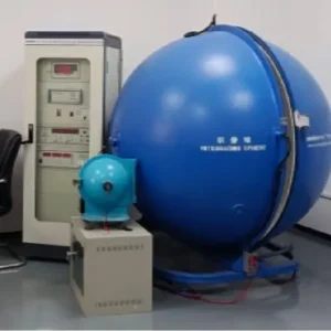
When we test batches for our international clients, we know that a single loose connection can ruin a seamless linear lighting effect continuity test 1. Ignoring weak spots during the initial inspection often leads to costly site repairs and frustrated project owners later.
To ensure COB solder joints are secure, first inspect them visually for a shiny, concave fillet rather than a dull, gray finish. Next, perform a continuity test using a multimeter to detect resistance above 1 ohm. Finally, apply a gentle flex test while the strip is powered to identify flickering caused by hidden micro-fractures.
Let's dive into the specific methods and standards we use to guarantee reliability in high-density lighting projects.
How can I visually identify a weak or "cold" solder joint on my high-density COB strips?
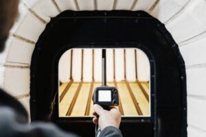
During our daily production line audits, catching visual defects early saves thousands in wasted material and labor thermal camera or IR thermometer 2. You generally do not need expensive automated optical inspection machines 3 to spot the most common soldering errors on a job site.
A healthy solder joint appears smooth, shiny, and volcano-shaped, indicating proper wetting across the pad. In contrast, a "cold" joint looks dull, grainy, or balled up on the surface without spreading. On high-density COB strips, also watch for scorched brown flux or blackening, which signals overheating that damages the delicate copper traces.
Visual inspection is your first line of defense. High-density COB (Chip-on-Board) strips 4 present a unique challenge compared to traditional SMD strips because the solder pads are incredibly small, often less than 0.5mm wide. In our factory, we use 20x magnification to examine these points, and I recommend you use a decent magnifying glass or a smartphone with a macro lens mode.
The "Volcano" vs. The "Ball"
The shape of the solder tells the entire story of the bond. You are looking for a concave "meniscus" or fillet. This looks like the sides of a volcano sloping gently from the wire down to the flat pad. This shape proves that the solder was hot enough to flow and "wet" the metal pad chemically.
If the solder looks like a round ball sitting on top of the pad, it is a reject. We call this "non-wetting 5." It means the solder has cooled around the wire but hasn't actually bonded to the PCB copper. It might hold for a day, but vibrations will eventually break it loose.
Detecting Cold Joints and Overheating
A "cold" joint happens when the soldering iron wasn't hot enough or was moved too quickly. These joints look frosty, grainy, or dull gray instead of shiny silver. They are brittle and have high electrical resistance. Conversely, because COB strips are dense, it is easy to accidentally overheat them. If you see the white PCB mask turning yellow or brown around the pad, the copper track underneath might have lifted from the board.
Visual Defect Indicators
Use this table to interpret what you see under magnification:
| Visual Symptom | Likely Diagnosis | Root Cause |
|---|---|---|
| Dull, grainy surface | Cold Solder Joint | Insufficient heat or movement during cooling. |
| Spherical, ball shape | Non-Wetting | Pad was oxidized or not heated enough. |
| Black/Brown residue | Overheating | Iron held too long; flux burned. |
| Cracked ring | Fractured Joint | Mechanical stress or thermal shock. |
| Pinholes in solder | Outgassing | Moisture in the PCB escaping during heating. |
What physical stress tests should I perform to ensure my LED strip connections are project-ready?
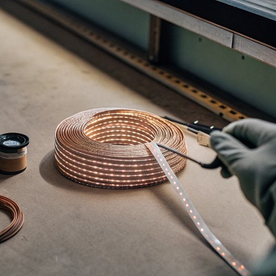
We always advise our partners in Australia and Germany to physically test strips before final installation. A static bench test often misses intermittent connection issues that only appear during the actual handling and mounting process.
Perform a "flex test" by gently bending the strip near the solder point to a 10mm radius while it is powered on. If the light flickers or dims, the joint is fractured. Additionally, a light tug test on the wires ensures mechanical strength, confirming the solder has bonded securely to both the wire strands and the PCB pad.
Visual checks are passive; physical tests are active. COB strips are flexible, but the solder itself is rigid. This interface—where the flexible board meets the rigid solder—is the most common point of failure.
The Gentle Flex Test
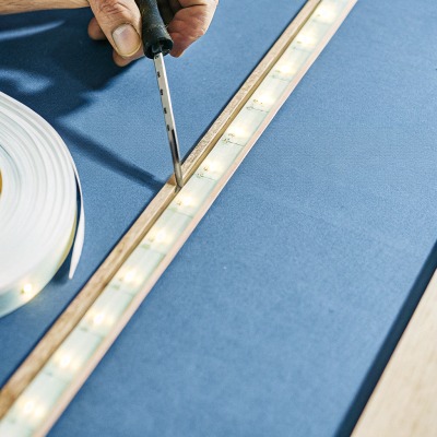
Do not install a strip without this test. Connect the strip to power so it lights up. Then, gently flex the PCB up and down near the soldered connection. Do not fold it like a piece of paper; just bend it slightly.
We are looking for intermittency. If the LEDs flicker, dim, or cut out for a split second while you are moving the strip, you have a "dry joint" or a micro-fracture. These cracks are often invisible to the naked eye but will open up when the strip expands from heat. In our production line, any flickering during handling triggers an immediate rework.
The Wire Tug Protocol
This test confirms mechanical integrity. Hold the PCB firmly in one hand and the wire in the other. Apply a gentle pull—roughly the force you would use to pull a sticky note off a desk. The wire should not move.
If the wire pulls out leaving a hole in the solder, it wasn't tinned properly. If the wire pulls the entire solder pad off the PCB (leaving a brown spot), the PCB was overheated and delaminated. Both are failures.
Stress Test Parameters
Here is how we quantify these manual tests in our QC protocols:
| Test Name | Action Description | Pass Criteria | Fail Criteria |
|---|---|---|---|
| Flex Test | Bend PCB 45° up/down near joint (Power ON). | Light remains 100% stable. | Any flicker, dimming, or blackout. |
| Tug Test | Pull wire axially with ~5N force (approx 0.5kg). | Wire remains fixed; PCB stays flat. | Wire slides out or pad lifts off board. |
| Twist Test | Twist wire 90° relative to pad. | Solder shows no cracks. | Visible hairline fracture appears. |
How do I verify that the soldering will withstand thermal expansion in my long-run installations?
In our R&D climate chamber, we simulate years of usage to prevent field failures. Thermal expansion 6 is the silent killer of COB strips in continuous-run projects, especially when high currents create significant heat cycles.
To simulate thermal stress, run the COB strip at full power for at least 60 minutes and monitor the solder joints with a thermal camera or IR thermometer. A temperature spike of more than 5°C at a specific joint compared to the surrounding PCB indicates high resistance and a likely future failure point.
High-density COB strips generate more heat than older SMD strips because the chips are packed so closely together. When you power them on, the copper tracks expand. When you turn them off, they contract. Solder is a metal alloy that does not expand at the exact same rate as the copper PCB. Over thousands of on/off cycles, this mismatch fatigues the joint.
The "Burn-In" Test
In professional manufacturing, we call this "burn-in." You should replicate a shorter version of this. Lay the strip out (uncoiled) and run it at its maximum rated voltage for an hour.
Why do this? A poor solder connection has higher electrical resistance. Resistance generates heat ($I^2R$). As the joint heats up, the metal expands, which might separate the contact further, increasing resistance even more. This is a "runaway" thermal event. If a joint fails this test, it will definitely fail inside an aluminum profile six months from now.
Using Thermal Imaging
You don't need a $5,000 lab camera; a smartphone attachment (like a FLIR One or Seek Thermal) works well for this. Scan the connection points.
The solder joint should be roughly the same temperature as the adjacent LED chips or slightly cooler (since the wire acts as a heat sink). If the solder joint is glowing bright red or white on the thermal screen—significantly hotter than the rest of the strip—it is a bottleneck. That heat is energy being wasted pushing current through a bad connection.
Temperature Delta Analysis
Use this guide to interpret your thermal readings:
| Temp Difference ($\Delta T$) vs PCB | Condition | Action Required |
|---|---|---|
| < 2°C | Excellent | No action; secure connection. |
| 2°C - 5°C | Acceptable | Monitor; likely safe for low power. |
| 5°C - 10°C | Warning | Re-flow the solder; resistance is too high. |
| > 10°C | Critical Failure | Cut and re-solder immediately; fire risk. |
What quality control standards should I look for to guarantee the long-term security of my COB solder points?
When we source raw materials and finalize production standards, we rely on strict benchmarks to ensure consistency. Knowing these specific metrics helps you filter out low-quality suppliers or verify your own work against professional grades.
Look for adherence to IPC-A-610 standards, specifically Class 2 or 3 for electronics reliability, which dictates fillet height and wetting angles. High-quality COB strips should also pass specific bend tests (IEC 60068) and have a stated failure rate of less than 0.1% per 1,000 hours under normal thermal cycling conditions.
For many DIYers or installers, "standards" sound like boring paperwork. But in our industry, they are the difference between a light that lasts 5 years and one that fails in 5 weeks. The gold standard for electronics assembly is IPC-A-610.
IPC-A-610 Basics for COB
You don't need to read the whole manual, but you should know what "Class 2" (Dedicated Service Electronic Products) requires.
- Wetting Angle: The angle between the solder and the pad must be less than 90 degrees. If it's over 90, it's a "ball" (bad). Ideally, it should be near 30-45 degrees.
- Fillet Height: The solder should climb up the wire strands. It needs to cover at least 50% of the wire diameter to be considered secure.
- Pad Coverage: The solder must cover 100% of the pad area intended for the connection.
Beyond the Certificate
When buying high-density COB strips, ask the supplier about their "Salt Spray Test" and "Vibration Test" results if you are near the coast or in high-traffic areas. Solder creates a galvanic couple; in salty air (like a beachfront villa in Australia), poor solder joints corrode faster.
A secure joint isn't just about electricity; it's about mechanical survival. High-quality manufacturers use solders with specific silver content (like SAC305 7) to improve flexibility and conductivity, rather than cheap lead-free alternatives that are brittle.
QC Checklist for Buyers
When inspecting a sample or datasheet, check these metrics:
| Metric | Professional Standard | Why it Matters |
|---|---|---|
| Solder Composition | SAC305 (Sn/Ag/Cu) | Silver adds strength and vibration resistance. |
| Flux Residue | "No-clean" or Cleaned | Acidic residue causes corrosion over time. |
| Wire Strain Relief | Gluing/Potting over Joint | Prevents mechanical stress from reaching the solder. |
| Trace Thickness | 2oz or 3oz Copper | Thicker copper dissipates heat better, protecting the joint. |
Conclusion
Ensuring your high-density COB LED strips are secure involves more than just hoping the lights turn on. By inspecting the visual shape of the fillet, performing active flex and tug tests, and checking for thermal hotspots, you can filter out failures before they are permanently installed. Taking these extra minutes for quality control prevents expensive rework and guarantees the professional finish your projects deserve.
Footnotes
- Explains what a continuity test is and how it's performed in electronics. ↩︎
- Differentiates between thermal cameras and IR thermometers for temperature measurement and inspection. ↩︎
- Provides a comprehensive guide to Automated Optical Inspection (AOI) technology in manufacturing. ↩︎
- Explains Chip-on-Board (COB) LED technology, its construction, and advantages. ↩︎
- Defines solder non-wetting defects, their causes, and impact on solder joints. ↩︎
- Explains the concept of thermal expansion and its implications for electronic assemblies and solder joints. ↩︎
- Describes SAC305 lead-free solder alloy, its composition, and properties for electronic soldering. ↩︎
- Provides a comprehensive guide to the IPC-A-610 standard for electronic assembly quality. ↩︎