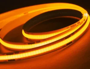
Have you ever noticed a red fabric looking dull gray under certain LED lights? That frustrating color distortion has sent many of our clients back to the drawing board mid-project.
High CRI (≥90) in COB LED strip lights is achieved by combining a precisely tuned blue LED chip with advanced multi-phosphor formulas—especially red-emitting phosphors—that fill spectral gaps and produce a smooth, sunlight-like spectrum across all visible wavelengths.
In this article, I will break down exactly how the chip and phosphor work together, why the R9 red value matters more than most people think, and how to balance color accuracy with brightness in your next project. Let's dig in.
How can I ensure the phosphor and chip combination in my COB LED strips consistently hits CRI 90+?
Over the years, our engineering team has tested hundreds of chip-and-phosphor pairings. The biggest lesson? A great blue chip alone will never get you to CRI 90+.
To consistently achieve CRI 90+ in COB LED strips, you need a high-quality blue chip tuned to 450–455 nm paired with a multi-phosphor blend that includes red nitride or KSF phosphors, all applied as a uniform layer and tightly controlled through binning management.
Understanding the Blue Chip Foundation
Every white LED starts with a blue semiconductor chip, typically made from Indium Gallium Nitride (InGaN) 1. This chip emits blue light at a specific peak wavelength, usually between 440 nm and 460 nm. For high-CRI work, we find that chips tuned to the 450–455 nm range offer the best excitation efficiency for the red and green phosphors that follow.
The chip itself does not determine CRI directly. Think of it as the engine in a car. It provides the energy, but it is the phosphor layer—the transmission—that shapes the final output. A poorly matched chip will under-excite or over-excite certain phosphors, leading to inconsistent color rendering.
The Multi-Phosphor Formula
Standard white LEDs use a single yellow YAG:Ce phosphor 2 over the blue chip. Blue light plus yellow phosphor equals white light. Simple, but flawed. The spectrum has a massive valley in the 600–700 nm deep red range. That valley is why reds look gray.
To push CRI above 90, manufacturers blend multiple phosphors together:
| Phosphor Type | Emission Range | Role in CRI |
|---|---|---|
| YAG:Ce (Yellow) | 520–580 nm | Base white conversion |
| β-SiAlON (Green) | 520–560 nm | Fills green gap, balances spectrum |
| Nitride Red 3 (e.g., CASN) | 610–660 nm | Fills deep red gap, boosts R9 |
| KSF:Mn (Red) | 630 nm (narrow-band) | Sharp red peak, less lumen loss |
When these phosphors are blended correctly, they absorb blue light and re-emit it across a broad, continuous spectrum. The result looks much closer to natural sunlight.
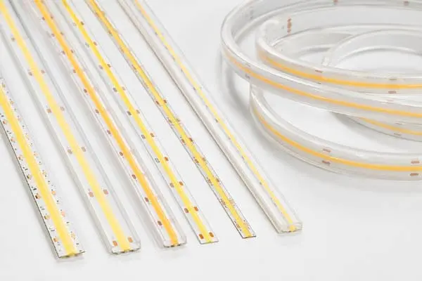
Why COB Makes a Difference
In a traditional SMD LED strip, each tiny LED has its own phosphor dot. Variations in phosphor thickness from chip to chip cause visible color inconsistency. COB technology 4 solves this. Multiple chips sit under one continuous phosphor layer. The light mixes uniformly before it exits. This means the multi-phosphor recipe is applied evenly, and the CRI stays consistent from one end of the strip to the other.
Binning: The Hidden Quality Gate
Even with a perfect phosphor formula, raw LED chips vary slightly in wavelength and brightness. Without strict binning—sorting chips into narrow performance groups—your CRI will drift between batches. On our production line, we use a 2-step or 3-step MacAdam ellipse binning standard 5. This keeps the color point tight enough that the human eye cannot detect differences between strips from different production runs.
There is a common misconception in this industry. Many people think swapping to a premium chip alone will deliver CRI 95. In reality, the chip is just the starting point. The real cost and complexity sit in the phosphor formula and the binning discipline. I have seen too many bargain "CRI 95" products that fall apart the moment you measure R9.
How do I prevent color variance across different batches when ordering high CRI COB LED strips for my project?
When we ship high-CRI COB strips to contractors in Germany and Australia, their number one concern is always the same: "Will the next batch look exactly like the last one?"
To prevent color variance across batches, demand tight MacAdam ellipse binning (3-step or less), request spectral test reports for every production lot, and work with a supplier who maintains phosphor formula consistency and incoming material traceability throughout the supply chain.
What Causes Batch-to-Batch Color Variance?
Color variance comes from three main sources: chip wavelength drift, phosphor ratio inconsistency, and process variation during the phosphor coating step. Even a 3 nm shift in the blue chip's peak wavelength can visibly change the final white output. Similarly, a slight change in the ratio of red to yellow phosphor will push the CRI up or down and shift the correlated color temperature (CCT).
The MacAdam Ellipse Standard
The MacAdam ellipse system measures how tightly grouped the color points of a batch of LEDs are. The smaller the ellipse, the less perceptible the color difference.
| MacAdam Step | Human Perception | Typical Use Case |
|---|---|---|
| 1-step | Imperceptible difference | Laboratory reference |
| 2-step | Barely noticeable to trained eye | Premium architectural lighting |
| 3-step | Slight difference, acceptable | High-end commercial lighting |
| 5-step | Noticeable side by side | Standard commercial lighting |
| 7-step | Obvious difference | Budget general lighting |
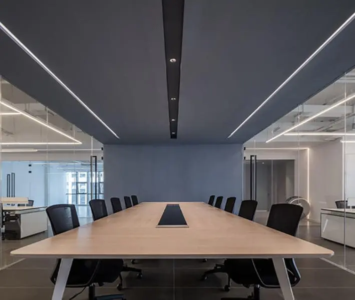
For high-CRI COB strips used in continuous cove lighting or wall washing, I always recommend specifying 3-step MacAdam or tighter. Anything looser, and you risk seeing color bands where two reels meet on the same wall.
Practical Steps You Can Take
First, ask your supplier for a spectral power distribution (SPD) report 6, not just a CRI number. The SPD shows you the full picture: the shape of the spectrum, the strength of the red peak, and whether the CCT is within your tolerance. Second, request chromaticity coordinate data 7 (CIE x, y values) for each batch. Compare them against your approved sample.
Third, lock down the phosphor formula with your supplier early. If your supplier switches phosphor vendors or adjusts the blend ratio mid-order to save costs, your color will shift. At Glowin, we maintain full traceability on our phosphor sourcing. When a client approves a sample, we record the exact phosphor lot, chip bin, and process parameters. This way, reorders match.
The Role of Thermal Management
Heat accelerates phosphor degradation. If the COB strip runs too hot due to poor heat sinking, the phosphor's output spectrum will shift over time—typically drifting toward blue as the red phosphor degrades faster. Proper aluminum profile mounting and adequate thermal design are not just about lifespan. They directly protect your CRI consistency over thousands of hours.
Why should I prioritize the R9 value in the phosphor formula to achieve true-to-life colors in my high-end installations?
In our experience working with lighting designers, one question comes up repeatedly once they start digging into spec sheets: "Why does this CRI 90 strip still make my client's red sofa look washed out?"
You should prioritize R9 because the general CRI (Ra) averages only eight pastel test colors and ignores deep red. A high R9 value—ideally above 50, and above 90 for premium work—proves the phosphor formula genuinely reproduces saturated reds, skin tones, and warm materials.
What Exactly Is R9?
CRI, or more precisely Ra, is the average score across eight specific test color samples (R1 through R8). These samples are all relatively muted pastels. R9 is a separate, extended test color—saturated deep red. It is not included in the Ra average. This means a strip can score Ra 90 while having an R9 as low as 0 or even negative. The red rendering would be terrible, but the headline CRI number looks fine on the data sheet.
This is the single biggest trap in the LED lighting industry. I have personally tested dozens of so-called CRI 95 products from low-cost sources and found R9 values below 20. At that level, red meat under a butcher counter looks brown. Red fabrics look muddy. Skin tones appear sickly.
Where R9 Matters Most
Think about any environment where warm colors are critical:
- Jewelry retail: Gold and ruby tones need saturated red light to sparkle.
- Art galleries and museums: Paintings with red pigments must be rendered faithfully.
- Hospitality: Food presentation relies on appetizing warm tones.
- Residential kitchens: Fresh produce should look vibrant, not dull.
- Fashion retail: Red, burgundy, and earth-toned fabrics must match what the customer sees in daylight.
How the Phosphor Formula Drives R9
The R9 value is almost entirely determined by the red phosphor component. Nitride-based red phosphors (like CASN or Sr2Si5N8:Eu2+) emit across a broad band centered around 620–650 nm. They are excellent at boosting R9 into the 90+ range, but they come with a notable efficiency penalty—more on that in the next section.
KSF:Mn phosphors 8 offer a narrower red emission peak around 630 nm. They are more efficient than nitrides but may not push R9 quite as high for ultra-premium applications.
| Phosphor Type | Typical R9 Range | Efficiency Impact | Best For |
|---|---|---|---|
| YAG:Ce only (no red) | -20 to 20 | None (baseline) | Budget CRI 70–80 strips |
| KSF:Mn added | 50–80 | Moderate lumen loss (5–10%) | Commercial CRI 90 strips |
| Nitride red added | 80–98 | Higher lumen loss (15–25%) | Premium CRI 95+ strips |
| KSF + Nitride blend | 70–95 | Balanced loss (10–18%) | High-end architectural strips |
Always Ask for the Full Color Rendering Report
My advice is simple: never accept a product based on a single Ra number. Ask your supplier for the full 15-sample rendering report (R1 through R15). Pay special attention to R9 (deep red), R13 (skin tone), and R15 (Asian skin tone). If a supplier cannot provide this data, that is a red flag. Reliable high-CRI COB strip manufacturers test every production lot with a calibrated integrating sphere and can hand you the full report within hours.
The real cost of a genuine high-CRI product sits in the phosphor and the quality management, not in the chip. When you see a price that seems too good to be true for CRI 95, the R9 data will almost always tell the real story.
How can I balance high CRI requirements with lumen efficiency in my custom COB LED strip specifications?
Every custom order we handle involves the same conversation at some point: the client wants museum-grade color rendering and warehouse-level brightness on the same strip. The physics make that very difficult.
Balancing high CRI with lumen efficiency requires choosing the right phosphor type—narrow-band KSF red phosphors lose fewer lumens than broad-band nitride reds—and compensating by slightly increasing LED density or drive current to recover the brightness gap without overheating.
Why High CRI Costs You Lumens
The physics is straightforward. When a phosphor converts blue light (short wavelength, high energy) into red light (long wavelength, low energy), the energy difference is lost as heat. This is called the Stokes shift 9. Red phosphors suffer a larger Stokes shift than yellow phosphors because the wavelength gap is bigger. On top of that, red phosphors tend to have lower quantum efficiency 10—they convert fewer blue photons into red photons.
The practical result: a CRI 95 COB strip is typically 15–25% dimmer than a CRI 80 strip using the same wattage and chip count. For a project that requires a specific lux level on a surface, this means you either need more strip length, higher power, or acceptance of a slightly lower CRI target.
Strategies to Recover Lost Lumens
There are several engineering levers we use when clients need both high CRI and strong output:
1. Use KSF phosphors where R9 >50 is sufficient. KSF's narrow emission band wastes less energy than broad nitride reds. You keep more lumens while still hitting CRI 90 with R9 in the 50–80 range.
2. Increase LED density. COB strips can be manufactured with more chips per meter. More chips at lower individual drive currents produce more total lumens with better thermal performance and longer life.
3. Optimize the chip's peak wavelength. A slight shift in the blue peak from 445 nm to 452 nm can improve the excitation efficiency of the chosen red phosphor, squeezing a few more lumens from the same power input.
4. Upgrade the encapsulant. High-refractive-index silicone encapsulants improve light extraction from the phosphor layer. This can recover 3–5% of the lumens lost to internal reflection.
Setting Realistic Expectations
Here is a rough guide for project planning:
| CRI Target | Expected Lumen Efficiency (lm/W) | Typical R9 | Best Application |
|---|---|---|---|
| CRI 80 | 140–170 lm/W | 0–30 | General commercial, warehouse |
| CRI 90 | 110–140 lm/W | 50–70 | Retail, hospitality, office |
| CRI 95 | 90–120 lm/W | 70–95 | Gallery, museum, luxury retail |
| CRI 97+ | 70–100 lm/W | 90+ | Photography, conservation |
These numbers are approximate and depend on the specific chip generation and phosphor quality. But they give you a realistic framework for comparing brightness targets against color accuracy goals.
When to Accept the Trade-Off
For a jewelry display case, no one cares if you lose 20% brightness. The diamonds need to sparkle with true white fire and the gold must glow warm. CRI 95+ with high R9 is non-negotiable.
For a parking garage, maximum lumens per watt wins every time. CRI 70 is perfectly fine, and no one is judging skin tones under fluorescent-style lighting.
Most projects fall somewhere in between. A high-end residential kitchen might do beautifully with CRI 90 and R9 above 50, paired with enough strip density to hit the desired lux level. The key is having an honest conversation about priorities before locking in specs.
On our production line, we often prototype two or three phosphor blends for a single project—one optimized for CRI, one for lumens, and one balanced in between. The client evaluates them under real conditions and picks the winner. This co-development approach avoids surprises after thousands of meters have been manufactured.
Conclusion
High CRI in COB LED strips comes down to phosphor engineering, strict binning, and honest R9 reporting—not marketing claims. Specify wisely, demand full spectral data, and partner with a supplier who understands the science behind every lumen.
Footnotes
- Wikipedia provides a comprehensive overview of InGaN as a semiconductor material for LEDs. ↩︎
- Replaced HTTP 403 link with a relevant Wikipedia section on YAG:Ce phosphor. ↩︎
- YujiLEDs discusses nitride red LED phosphor's role in high CRI and low CCT white LEDs. ↩︎
- ViewSonic explains COB LED technology, its manufacturing process, and advantages over other LED types. ↩︎
- Replaced HTTP 404 link with a comprehensive Wikipedia article on MacAdam ellipses. ↩︎
- Replaced HTTP 404 link with a Wikipedia article explaining spectral power distribution, ensuring HTTPS. ↩︎
- Replaced HTTP 404 link with a relevant Wikipedia section on CIE 1931 color space and chromaticity coordinates, ensuring HTTPS. ↩︎
- Luminus Devices provides an introduction to KSF phosphor LEDs, highlighting their narrow-band emission. ↩︎
- Grokipedia defines Stokes shift as the energy difference between absorption and emission spectra in luminescent materials. ↩︎
- Replaced HTTP 404 PDF link with a Wikipedia article defining quantum efficiency. ↩︎