Many of clients come to us confused about why their tunable white strips look patchy or shift to greenish tones mid-range. The problem usually is not the controller. It is the strip itself — specifically, how well the two sets of LED chips inside it are matched.
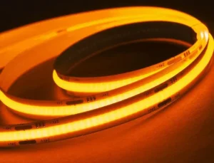
Adjustable color temperature COB LED strip lights work by embedding two groups of white LED chips — typically warm white (2700K) and cool white (6500K) — onto a single dense COB board. A CCT controller then adjusts the power ratio between both groups, blending their output to produce any intermediate white tone across the full Kelvin range.
That sounds simple in theory, but in practice, the engineering behind smooth, consistent color mixing is anything but straightforward. Below, I will walk you through the real technical principles at play — from chip-level mixing to controller matching, color consistency, and the dot-free advantage of COB packaging 1.
How do dual-chip COB structures actually mix warm and cool light within my installations?
When we first started developing tunable white COB strips on our production line, the biggest surprise was how much the physical chip layout 2 affected color blending. A bad layout made the strip look striped — warm patches next to cool patches — even when the controller was set to a mid-range tone.
Inside every adjustable CCT COB strip, warm white and cool white LED chips are densely alternated along the PCB. The controller drives each group at a different intensity using PWM dimming, and the phosphor encapsulation layer blends their output into a single perceived color temperature visible to the human eye.
How the Two Chip Groups Are Arranged
A tunable white COB strip is not just one type of LED chip repeated hundreds of times. It contains two distinct populations of chips. One group uses a phosphor blend that emits warm white light, typically around 2700K–3000K. The other group uses a different phosphor that emits cool white light, usually around 5700K–6500K.
These chips are mounted directly onto a flexible printed circuit board in an alternating pattern. The alternation is key. If you placed all the warm chips on the left and all the cool chips on the right, the strip would never look uniform. Instead, warm and cool chips are interleaved as closely as possible — sometimes in a W-C-W-C sequence — so that when both are lit, the eye perceives a single blended tone.
The Role of PWM in Color Mixing
The controller manages each chip group through a separate electrical channel. Most systems use Pulse Width Modulation 3, or PWM. PWM rapidly switches each channel on and off at a frequency too fast for the eye to detect. By varying the duty cycle — the percentage of time each channel is "on" — the controller changes the effective brightness of each chip group.
| Setting | Warm White Channel | Cool White Channel | Perceived CCT |
|---|---|---|---|
| Full warm | 100% duty cycle | 0% duty cycle | ~2700K |
| Mid-warm | 70% duty cycle | 30% duty cycle | ~3500K |
| Neutral | 50% duty cycle | 50% duty cycle | ~4000K |
| Mid-cool | 30% duty cycle | 70% duty cycle | ~5000K |
| Full cool | 0% duty cycle | 100% duty cycle | ~6500K |
Why Chip Matching Matters More Than You Think
I personally believe the real test of a tunable white strip is not the range of Kelvin values it can display. It is how the strip looks at mid-range values — around 3500K to 4500K. This is where poor chip matching becomes visible.
If the warm chip group is significantly brighter than the cool group, the strip will look pinkish when both channels are partially on. If the cool group is brighter, it will lean green. Our engineers spend considerable time binning and matching the luminous flux 4 of both chip groups so that the transition from warm to cool is visually smooth. This is the difference between a specification sheet that says "2700K–6500K" and a strip that actually looks good at every point in that range.
The phosphor encapsulation layer 5 on top of the chips also plays a blending role. In COB strips, this layer is continuous rather than segmented, which helps diffuse and merge the two light sources into one uniform output.
How can I ensure the color consistency of adjustable CCT strips remains stable across my entire project?
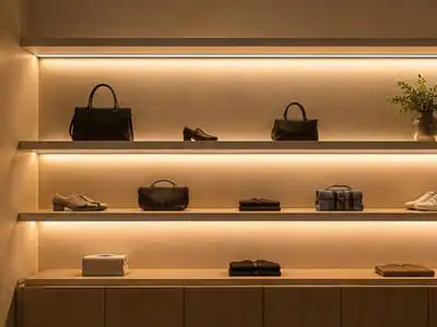
We have seen projects where one roll of tunable white strip looks perfect, and the next roll from a different batch shifts noticeably when placed side by side. For contractors working on hotel corridors or retail displays, this is a dealbreaker.
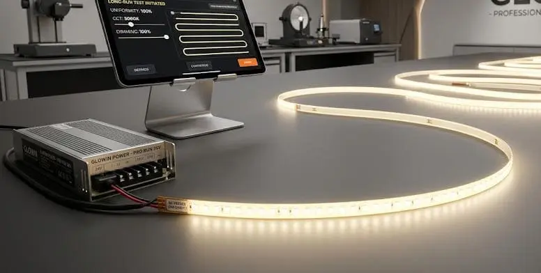
To ensure stable color consistency across an entire project, you need LED strips from tightly binned chip batches, consistent phosphor application, proper thermal management with aluminum profiles, and identical power supply and controller configurations for every strip segment in the installation.
What Causes Color Inconsistency?
Color inconsistency in tunable white strips comes from several sources. The most common one is chip binning variance 6. LED chips are manufactured in large quantities, and no two chips are perfectly identical. Manufacturers sort chips into "bins" based on their measured color coordinates and luminous flux. Tighter bins mean closer matches.
When we source chips for a project order, we specify the same bin code for both the warm and cool groups across every reel. This is one reason why project-grade strips cost more than commodity strips — the binning tolerance is much narrower.
Factors That Affect On-Site Consistency
Even with perfectly matched strips, installation conditions can introduce variance.
| Factor | How It Affects Consistency | Mitigation |
|---|---|---|
| Voltage drop 7 over long runs | Strips dim and shift color at the far end | Use 24V strips, inject power from both ends, or add mid-point power feeds |
| Thermal environment | Excess heat shifts phosphor output and reduces brightness | Mount strips on aluminum heat-sink profiles |
| Controller mismatch | Different controller models may output slightly different PWM frequencies | Use the same controller model and firmware for the entire project |
| Power supply variation | Unstable voltage causes flickering and color drift | Use regulated constant-voltage drivers rated at no more than 80% load |
| Strip batch mixing | Different production batches may have slight phosphor differences | Order all strips for one project from a single production batch |
The Importance of Thermal Management
COB strips pack a lot of chips into a small area. That density is great for visual uniformity, but it generates more heat per linear meter than a comparable SMD strip. Heat shifts the phosphor's emission characteristics, which means a strip running hot will look slightly different from a strip running cool.
In our experience exporting to Australia, where ambient temperatures in ceiling voids can climb above 40°C in summer, we always recommend aluminum extrusion profiles. The profile acts as a heat sink. It draws heat away from the PCB and dissipates it along the length of the channel. Without it, you risk not only color drift but also accelerated LED depreciation.
Maintaining CRI Across the Range
Color Rendering Index 8, or CRI, measures how accurately a light source reveals the true colors of objects. High-quality tunable white strips maintain a CRI above 90 across the entire 2700K to 6500K range. Cheaper strips may hit Ra 90 at full warm but drop to Ra 80 at mid-range values. For retail, hospitality, and residential projects, specifying CRI ≥ 90 at all CCT points is essential.
What technical factors should I consider when matching controllers to my adjustable color temperature COB strips?
Choosing the wrong controller is one of the fastest ways to ruin an otherwise good tunable white installation. When we help clients spec out their projects, the controller conversation often takes longer than the strip selection itself.
When matching a controller to adjustable CCT COB strips, you must verify voltage compatibility (12V or 24V), total wattage capacity with at least 20% headroom, dual-channel output for warm and cool, PWM frequency compatibility, and signal protocol support such as RF, DALI, Zigbee, or Matter for your specific automation needs.
Voltage and Power Sizing
Every tunable white CCT strip operates on low-voltage DC — either 12V or 24V. The controller must match the strip's voltage exactly. Sending 24V to a 12V strip will damage it immediately.
Power sizing is the next step. Calculate the total wattage of all connected strip segments. Then choose a controller rated for at least 120% of that total. This follows the common industry guideline of not exceeding 80% of rated capacity. Running a controller at full load generates excess heat, shortens its life, and can cause dimming instability.
Dual-Channel Output
A tunable white strip has two electrical channels — one for warm, one for cool. The controller must have dedicated dual-channel output. Do not confuse a single-color dimmer or an RGB controller with a CCT controller. An RGB controller has three channels (red, green, blue) and cannot properly drive a two-channel tunable white strip without adaptation.
| Controller Type | Channels | Compatible With CCT Strip? | Notes |
|---|---|---|---|
| Single-color dimmer | 1 | No | Only dims one channel; cannot mix CCT |
| CCT / Dual white controller | 2 | Yes | Purpose-built for warm + cool mixing |
| RGB controller | 3 | Not directly | Can sometimes be adapted but wastes a channel and may confuse wiring |
| RGBW controller | 4 | Not directly | Overkill and may cause signal mismatch |
| RGB+CCT controller | 5 | Yes (if wired correctly) | Used for RGB + tunable white strips only |
PWM Frequency Considerations
Not all PWM frequencies are equal. Low-frequency PWM — below about 500 Hz — can cause visible flicker, especially on camera. For commercial and hospitality installations, we recommend controllers with PWM frequencies above 1 kHz. Some high-end controllers operate at 20 kHz or above, which eliminates flicker entirely and is often required for broadcast or video production environments.
Signal Protocols and Smart Integration
Modern tunable white systems increasingly connect to building automation and smart home platforms. The signal protocol determines how the controller receives its instructions.
RF (radio frequency) remotes are the simplest option and work well for standalone installations. For larger or more integrated projects, DALI (Digital Addressable Lighting Interface 9) is the professional standard in commercial buildings. It allows individual addressing of each controller on a shared bus. Zigbee and Matter are gaining traction in residential and light commercial smart home applications, offering wireless mesh networking and voice control compatibility.
When we work with design firms in Germany, DALI compatibility is almost always required for project bids. In the Australian market, Zigbee and WiFi-based controllers are more common in residential renovations. Choosing the right protocol at the specification stage saves significant rework later.
Wiring Polarity and Distance
Tunable white strips typically use a three-wire or four-wire connection: positive voltage, warm white negative, and cool white negative (for common-anode designs). Reversing the warm and cool wires will not damage the strip, but it will invert the controller's behavior — turning the "warm" slider into a "cool" output and vice versa. Always label wires during installation.
For runs longer than 5 meters, voltage drop becomes a concern. Thicker gauge wire or additional power injection points help maintain consistent brightness and color across the full length.
How does the dot-free COB technology improve the visual uniformity of my adjustable color temperature lighting?
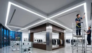
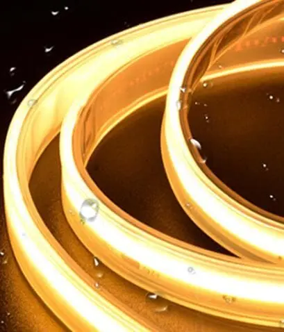
One complaint we hear repeatedly from contractors is the "polka dot" look of traditional SMD LED strips — especially when installed in aluminum profiles with clear or lightly frosted diffusers. COB technology was specifically developed to solve this problem.
COB (Chip-on-Board) technology eliminates visible LED dots by mounting hundreds of tiny chips per meter directly onto the PCB and covering them with a continuous phosphor layer. This creates a seamless, uniform line of light that remains visually smooth across all color temperature settings from warm to cool.

COB vs. SMD: A Visual Comparison
Traditional SMD (Surface Mount Device) LED strips place individual LED packages at intervals along the PCB — typically every 5 mm to 16 mm depending on density. Each LED package is a discrete point of light. When you look at the strip directly, or through a thin diffuser, you see individual bright spots separated by darker gaps.
COB strips take a fundamentally different approach. Instead of using pre-packaged LEDs, COB strips mount bare LED dies directly onto the PCB at extremely high density — often 480 to 720 chips per meter or more. The entire array is then covered with a single continuous phosphor and silicone encapsulation layer. This layer acts as both a color-conversion medium and a diffuser, merging the output of all the individual chips into one unbroken line of light.
Why This Matters More for Tunable White
The dot-free advantage of COB is especially important in tunable white applications. In an SMD tunable white strip, you can sometimes see alternating warm and cool LED dots through the diffuser. When both channels are active at intermediate CCT values, this can create a "striped" or "speckled" appearance — warm dots next to cool dots, rather than a single blended tone.
COB avoids this entirely. Because the phosphor layer is continuous and the chips are so densely packed, the warm and cool outputs merge physically within the encapsulation layer before the light even exits the strip. The result is a cleaner blend at every CCT setting.
Practical Benefits for Installers and Designers
For installations where the strip is visible — such as open shelving, cove lighting, or under-cabinet applications — COB tunable white strips offer a significantly more refined aesthetic. They also reduce the need for heavy frosted diffusers, which can cut light output by 20% to 40%. A lighter diffuser or even a clear lens can be used with COB strips while still maintaining a smooth appearance.
From a project perspective, this simplifies specification. Designers can focus on the strip and profile combination without worrying about whether the diffuser is thick enough to hide individual LED dots.
Density and Its Trade-Offs
Higher chip density does come with trade-offs. More chips per meter means more heat per meter. This is why aluminum profiles are not optional for high-density COB strips — they are essential. The PCB alone cannot dissipate enough heat to keep the chips within their rated temperature range. Without proper heat sinking, the strip will experience accelerated lumen depreciation and potential color shift over time.
Additionally, higher-density COB strips tend to have more cut points per meter, but each cut point must be precise. Cutting in the wrong place damages the continuous phosphor layer and can expose bare chips. Our strips are clearly marked with cut lines and solder pads to minimize installation errors.
Conclusion
Adjustable color temperature COB LED strip lights combine dense chip packaging with dual-channel white mixing to deliver seamless, tunable lighting. Understanding chip matching, controller selection, thermal management, and COB's dot-free advantage helps you specify and install these systems with confidence.
Footnotes
- Explains Chip-on-Board (COB) LED technology and its advantages in display devices. ↩︎
- Details how LED chip arrangement on a PCB affects light distribution and reliability. ↩︎
- Replaced with an authoritative Wikipedia article explaining Pulse Width Modulation. ↩︎
- Defines luminous flux as the measure of the perceived power of visible light emitted by a source. ↩︎
- Discusses the development of robust phosphor encapsulant materials to improve LED efficiency and lifetime. ↩︎
- Explains LED chip binning as a quality control process for consistent color and brightness. ↩︎
- Explains voltage drop in LED strip lights and methods to prevent it for consistent brightness. ↩︎
- Replaced with an authoritative Wikipedia article on High-CRI LED lighting and Color Rendering Index. ↩︎
- Introduces DALI as a dedicated protocol for digital lighting control, enabling robust and scalable networks. ↩︎
- Highlights the significant impact of thermal management on LED lifetime, performance, and cost. ↩︎