
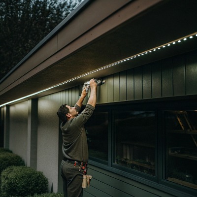
Wir versenden Tausende Meter LED-Streifen an Auftragnehmer, die Hotel-Lobbys, Einzelhandelsfassaden und Lagerausbauten realisieren — und die häufigste Frage betrifft nicht das LED selbst, sondern wie man es richtig mit Strom versorgt.
Das Design der LED-Streifenverdrahtung für Großprojekte erfordert die Aufteilung der Installation in parallel versorgte Zonen, die Dimensionierung der Netzteile mit mindestens einer Sicherheitsmarge von 20%, die Verwendung von Stromversorgungsanschlusspunkten alle 5 Meter für 12V-Streifen und die Auswahl dickerer Kabelquerschnitte, um Spannungsverluste bei langen Verteilungsstrecken zu minimieren.
Dieser Leitfaden führt Sie durch den gesamten Entwicklungsprozess — von der Lastberechnung und Spannungswahl bis hin zur Verkabelungstopologie, Strominjektionsstrategie und maßgeschneiderten Steckverbinderlösungen LED-Streifenverkabelung 1. Wenn Sie ein Auftragnehmer, Großhändler oder Lichtplaner sind, der eine große LED-Streifeninstallation plant, decken die unten stehenden Abschnitte genau das ab, was Sie benötigen, um konsistente und zuverlässige Ergebnisse zu erzielen.
Wie kann ich die Gesamtleistung für mein groß angelegtes LED-Streifenprojekt in Deutschland berechnen?
Wenn wir Kunden in Deutschland und Australien bei der Projektplanung unterstützen, fragen unsere Ingenieure zuerst nach der Gesamtlänge des Streifens und der Wattzahl pro Meter — denn die falsche Stromplanung ist die häufigste Ursache für Probleme Gesamtleistungsaufnahme 2.
Um die gesamte Leistungsaufnahme zu berechnen, multiplizieren Sie die Gesamtlänge Ihres LED-Streifens in Metern mit der Wattzahl pro Meter des Streifens und multiplizieren Sie das Ergebnis dann mit 1,2, um eine Sicherheitsmarge von 20 % hinzuzufügen. Dies gibt Ihnen die minimale Stromversorgungskapazität, die Sie benötigen, um das System sicher und zuverlässig zu betreiben.
Warum eine genaue Lastberechnung wichtig ist
Ein Netzteil, das zu klein ist, wird überhitzen, flackern oder bei Belastung abschalten. Ein viel zu großes Netzteil verschwendet Geld und Platz. Das Ziel ist, einen optimalen Bereich zu finden: genug Spielraum für Sicherheit, aber nicht so viel, dass Sie für Kapazität bezahlen, die Sie nie nutzen.
Hier ist die Grundformel:
Gesamtleistung des Streifens (W) = Gesamtlänge des Streifens (m) × Wattzahl pro Meter (W/m)
Dann wenden Sie Ihren Sicherheitszuschlag an:
Minimale PSU-Kapazität (W) = Gesamtleistung des Streifens × 1,2
Zum Beispiel, wenn Sie 80 Meter Streifen mit 14,4 W/m haben, beträgt die Gesamtleistung des Streifens 1.152 W. Multiplizieren Sie mit 1,2 und Sie benötigen mindestens 1.382 W Netzteilkapazität.
Eine praktische Lastberechnungstabelle
| Streifenlänge (m) | Wattzahl pro Meter (W/m) | Gesamtleistung des Streifens (W) | Mit 20% Sicherheitsmarge (W) |
|---|---|---|---|
| 50 | 9.6 | 480 | 576 |
| 80 | 14.4 | 1,152 | 1,382 |
| 120 | 19.2 | 2,304 | 2,765 |
| 200 | 14.4 | 2,880 | 3,456 |
Vergessen Sie nicht, Zubehör zu berücksichtigen
Ihre Gesamtlast sollte auch alle Controller, Verstärker oder Signalverstärker im Stromkreis enthalten. Diese verbrauchen ebenfalls Strom. Wenn Sie RGB- oder abstimmbare weiße Streifen verwenden, kann der Controller je nach Modell selbst 5–15 W verbrauchen. Bei einem 200-Meter-Projekt summieren sich diese kleinen Lasten.
Teilen Sie das Budget auf Zonen auf
Aus unserer Erfahrung mit dem Versand an große australische Ausbauprojekte empfehlen wir immer, die Gesamtleistung auf Zonen aufzuteilen. Anstatt einer einzigen großen 3.000-W-Stromversorgung verwenden Sie drei oder vier kleinere Einheiten, die näher an jeder Zone platziert sind. Dieser Ansatz reduziert Kabellängen, senkt Spannungsabfall 3 das Risiko und erleichtert die Fehlersuche erheblich. Wenn eine Versorgung ausfällt, wird nur eine Zone dunkel – nicht das ganze Gebäude.
Ein häufiger Fehler, den wir sehen, ist, dass Käufer die Gesamtleistung korrekt berechnen, dann aber versuchen, alles von einer einzigen zentralen Versorgung mit langen Kabelwegen zu betreiben. Die Mathematik mag auf dem Papier richtig aussehen, aber die Physik des Spannungsabfalls über die Entfernung wird das Ergebnis ruinieren. Kombinieren Sie Ihre Lastberechnung immer mit einem Verdrahtungsplan.
Was ist der beste Weg, um Spannungseinbrüche bei langen Beleuchtungsstrecken zu verhindern?
Dies ist die größte Kopfschmerzursache, von der wir von Auftragnehmern hören – der Streifen sieht in der Nähe der Stromversorgung perfekt aus, dimmt aber auf halber Strecke merklich ab, und manchmal leuchtet das ferne Ende kaum noch.
Der beste Weg, um Spannungsabfall zu verhindern, besteht darin, Parallelschaltungen anstelle von Kettenverschaltungen zu verwenden, 24V- oder 48V-LED-Streifen gegenüber 12V für längere Strecken zu wählen, dickere Kabelquerschnitte für die Verteilung zu verwenden und regelmäßig Stromversorgungsanschlüsse hinzuzufügen — typischerweise alle 5 Meter bei 12V oder alle 10 Meter bei 24V Streifen.
Warum Spannungsabfall auftritt
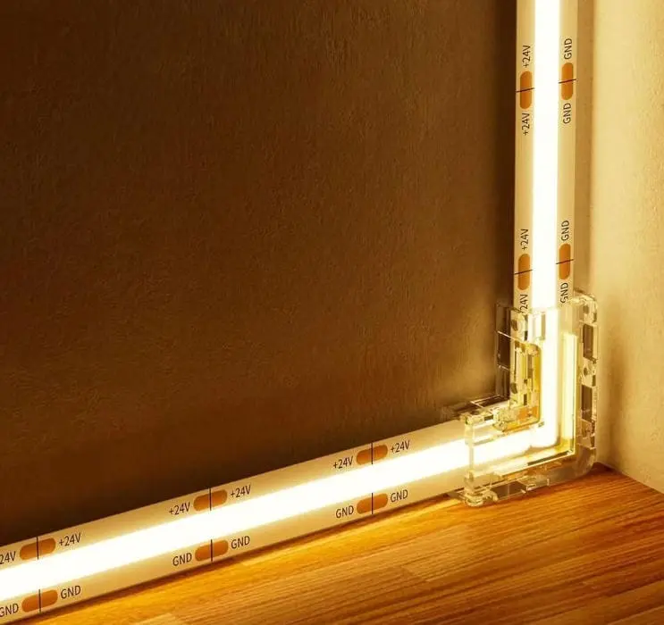
LED-Streifen sind Niederspannungsgeräte. Bei 12 V verursacht selbst ein geringer Widerstand in den Kupferbahnen oder Verbindungskabeln einen messbaren Spannungsverlust. Je weiter der Strom von der Stromversorgung fließt, desto mehr Spannung geht als Wärme im Leiter verloren. Wenn Sie bei einem 12-V-Streifen 8 oder 10 Meter von der Versorgung entfernt sind, haben Sie möglicherweise genug Spannung verloren, dass die LEDs am Ende merklich dunkler sind.
Wählen Sie die richtige Systemspannung
Eine der einfachsten Entscheidungen, die Sie frühzeitig in einem Projekt treffen können, ist die Wahl eines Streifens mit höherer Spannung. Hier ist ein Vergleich von 12 V, 24 V und 48 V:
| Parameter | 12V-Leiste | 24V-Leiste | 48V-Leiste |
|---|---|---|---|
| Strom für 14,4 W/m (pro Meter) | 1,2 A | 0,6 A | 0,3 A |
| Typischer Maximalbetrieb bei Einzelzufuhr | ~5 m | ~10 m | ~15–20 m |
| Schweregrad des Spannungsabfalls | Hoch | Mäßig | Niedrig |
| Komponentenverfügbarkeit | Sehr breit | Breit | Wachsend |
| Beste Anwendungsfälle | Kurze Läufe, kleine Installationen | Die meisten großen Projekte | Sehr lange Läufe, hohe Leistung |
Für nahezu jedes groß angelegte Projekt ist 24V die bessere Standardoption. Es halbiert den Strom im Vergleich zu 12V, was den Spannungsabfall bei gleicher Drahtstärke und Entfernung ungefähr halbiert. Wenn Sie sehr lange architektonische Kanten oder Fassadenbeleuchtung betreiben, sind 48V-Systeme eine Überlegung wert.
Parallele Verkabelung verwenden, nicht Serienschaltung
Wenn Sie Streifen nacheinander end-zu-Ende verbinden, trägt der erste Streifen den gesamten Strom für alle nachfolgenden Streifen. Dies überlastet die Kupferbahnen und verursacht einen allmählichen Spannungsabfall. In einer parallele Verkabelung 4 Anordnung verbindet sich jeder Streifenabschnitt unabhängig mit der Stromversorgung. Dies hält die Spannung an jedem Abschnitt konstant.
Denken Sie daran wie bei der Sanitärinstallation: Ein langer, schmaler Rohr verliert Druck am Ende, aber viele kurze Rohre, die von einer Hauptleitung abzweigen, erhalten alle den vollen Druck.
Strategie der Stromeinspeisung
Stromeinspeisung bedeutet, frische Spannung an Zwischenpunkten entlang des Streifens einzuspeisen. Stromeinspeisungspunkte 5 Sie führen ein separates Paar Drähte von der Stromversorgung (oder einem nahegelegenen Verteilerblock) zu dem Streifen an diesen Einspeisepunkten. Dadurch wird die Spannung wiederhergestellt, die sonst abfallen würde.
Eine praktische Faustregel: Einspeisung alle 5 Meter bei 12V-Streifen und alle 10 Meter bei 24V-Streifen. Für hochdichte Streifen, die mehr als 20 W/m ziehen, verkürzen Sie diese Intervalle. Unsere Ingenieure testen immer die tatsächliche Spannung am Ende jedes Abschnitts, bevor sie einen Verkabelungsplan freigeben.
Drahtstärke ist wichtig
Der Draht zwischen Ihrer Stromversorgung und der LED-Leiste ist genauso wichtig wie die Leiste selbst. Dünner Draht über eine lange Strecke verursacht bereits vor Erreichen der Leiste einen eigenen Spannungsabfall. Verwenden Sie dickeren Draht (niedrigere AWG-Nummer 6) für längere Verteilungsstrecken. dickere Drahtstärken 7
| Einwegdistanz (m) | Maximalstrom (A) | Empfohlener Drahtquerschnitt (AWG) |
|---|---|---|
| Bis zu 5 | 5 | 18 AWG |
| 5–10 | 5 | 16 AWG |
| 10–20 | 5 | 14 AWG |
| 10–20 | 10 | 12 AWG |
| 20–30 | 10 | 10 AWG |
Dies sind allgemeine Richtlinien. Überprüfen Sie stets anhand Ihrer spezifischen Last und des akzeptablen Spannungsabfalls (typischerweise unter 3–5%).
Wenn wir kundenspezifische Kabelbäume für unsere OEM-Kunden entwerfen, passen wir die Drahtstärke sowohl an den Strom als auch an die Entfernung vom Versorgungspunkt zum entferntesten Punkt der Leiste an. Diese Liebe zum Detail unterscheidet eine professionelle Installation von einer, die zu schwache, ungleichmäßige Beleuchtung führt.
Wie stelle ich eine gleichmäßige Helligkeit und Farbqualität auf meiner gesamten Projektseite sicher?
In unserem Testlabor haben wir gesehen, dass RGB-Leisten am Ende einer 10-Meter-Strecke von warmweiß zu einem rosafarbenen Ton wechseln — und das war auf der Werkbank, noch nicht einmal installiert. Bei einem echten Einsatz vor Ort sind die Probleme noch größer, da die Kabel länger sind und die Verbindungen weniger kontrolliert werden.
Gleichmäßige Helligkeit und Farbe erfordern abgestimmtes LED-Binning, eine einheitliche Stromversorgung durch parallele Zonen und Einspeisepunkte, synchronisierte Steuerungen für RGB- oder dimmbare Weißsysteme sowie eine ordnungsgemäße Wärmeverwaltung mit Aluminiumprofilen, um hitzebedingte Farbverschiebungen und Verschlechterungen zu verhindern.

Die Grundursachen für Inkonsistenz
Es gibt drei Hauptgründe, warum LED-Streifen bei einer großen Installation ungleichmäßig aussehen:
- Spannungsabfall — Niedrigere Spannung am entfernten Ende bedeutet weniger Strom durch die LEDs, was die Helligkeit verringert und die Farbtemperatur verschiebt.
- LED-Binning-Variation — LEDs aus verschiedenen Fertigungsbatches können leicht unterschiedliche Farbtemperaturen oder Helligkeitsstufen aufweisen, selbst wenn sie die gleiche Modellnummer haben.
- Wärmeeffekte — LEDs, die heißer laufen, verschieben ihre Farbe und verlieren schneller an Helligkeit als LEDs, die richtig gekühlt werden.
Lösung des Spannungsproblems
Dies ist dasselbe Problem wie im vorherigen Abschnitt, aber aus visueller Perspektive. Selbst ein Spannungsabfall von 5% kann einen sichtbaren Helligkeitsunterschied zwischen dem nahen und dem entfernten Ende eines Streifens verursachen. Bei RGB-Streifen ist es noch schlimmer: Die Rot-, Grün- und Blaukanäle fallen bei unterschiedlichen Raten ab, was zu einer Farbverschiebung führt — nicht nur zu einer Dimmerung.
Die Lösung ist dieselbe: Parallelschaltung, Strominjektion, höherspannungsfähige Streifen und dickere Verteilungsdrähte. Für farbkritische Projekte wie Einzelhandelsdisplays, Hotel-Lobbys oder Museumbeleuchtungen müssen Sie die Injektionsintervalle möglicherweise noch weiter verkürzen. Bei High-CRI-RGB-Streifen empfehlen wir eine Injektion alle 3–4 Meter bei 12V und alle 7–8 Meter bei 24V.
LED-Binning und Batch-Konsistenz
Wenn wir LEDs für unsere Produktionsläufe beziehen, legen wir engen Binning fest — das bedeutet, alle LEDs in einem Batch fallen in einen engen Bereich von Farbtemperatur und Helligkeit. Das übersehen viele Einkäufer. Wenn Sie Streifen von verschiedenen Lieferanten oder sogar verschiedenen Chargen desselben Lieferanten bestellen, können die LEDs bei seitlicher Anordnung unterschiedlich aussehen.
Unsere Empfehlung: Bestellen Sie alle Streifen für ein einzelnes Projekt in einer Charge. Wenn Sie später nachbestellen müssen, bitten Sie den Lieferanten um denselben LED-Bin-Code. Bei Glowin dokumentieren und teilen wir Bin-Daten mit unseren OEM-Partnern, damit sie die visuelle Konsistenz über die Phasen eines mehrstufigen Projekts hinweg aufrechterhalten können.
Wärmemanagement
Hitze ist der stille Killer der LED-Konsistenz. Ein Streifen, der direkt auf Gipskarton montiert ist, speichert Wärme gegen die LEDs. Im Laufe der Zeit — manchmal innerhalb von Monaten — verschlechtern sich die LEDs an den heißesten Punkten schneller, was zu ungleichmäßiger Helligkeit und Farbverlauf entlang des Streifens führt.
Die Lösung ist einfach: Verwenden Sie Aluminium-Extrusionsprofile. Aluminium wirkt als Wärmesenke, zieht Wärme von den LEDs weg und dissipiert sie in die umgebende Luft. Bei geschlossenen oder eingelassenen Installationen stellen Sie sicher, dass Luftzirkulation um das Profil vorhanden ist. In hoch-ambienten Umgebungen (über 40°C) verringern Sie die Leistung des Streifens oder wählen Sie ein Produkt mit niedrigerer Dichte.
Controller-Synchronisation
Für RGB, RGBW oder einstellbare Weißsysteme, die mehrere Zonen umfassen, kann jede Zone einen eigenen Controller oder Verstärker haben. Wenn diese nicht synchronisiert sind, treten sichtbare Zeitunterschiede bei Farbwechseln oder Dimm-Übergängen auf. Verwenden Sie einen Master-Controller mit Signalausgabe an alle Zonen oder wählen Sie ein System wie DMX oder DALI 8 das eine Frame-Level-Synchronisation bietet.
Wenn mehrere Netzteile verschiedene Zonen versorgen, aber einen einzigen Controller teilen, verbinden Sie immer deren Masse (negativ) Anschlüsse miteinander — dies wird als gemeinsamer Masseanschluss bezeichnet. Ohne ihn hat das Steuersignal keine konsistente Referenz, und die Streifen können sich unvorhersehbar verhalten.
Kann ich meine Verkabelung und Stromanschlüsse anpassen, um meinen Installationsprozess zu beschleunigen?
Unser Team hat mit Auftragnehmern gearbeitet, die mehr Zeit vor Ort mit Crimpen von Anschlüssen und Löten von Verbindungen verbrachten, als tatsächlich den Streifen zu montieren — und das ist ein Problem, das wir mit vorkonfektionierten, plug-and-play Verkabelungssätzen lösen wollten.
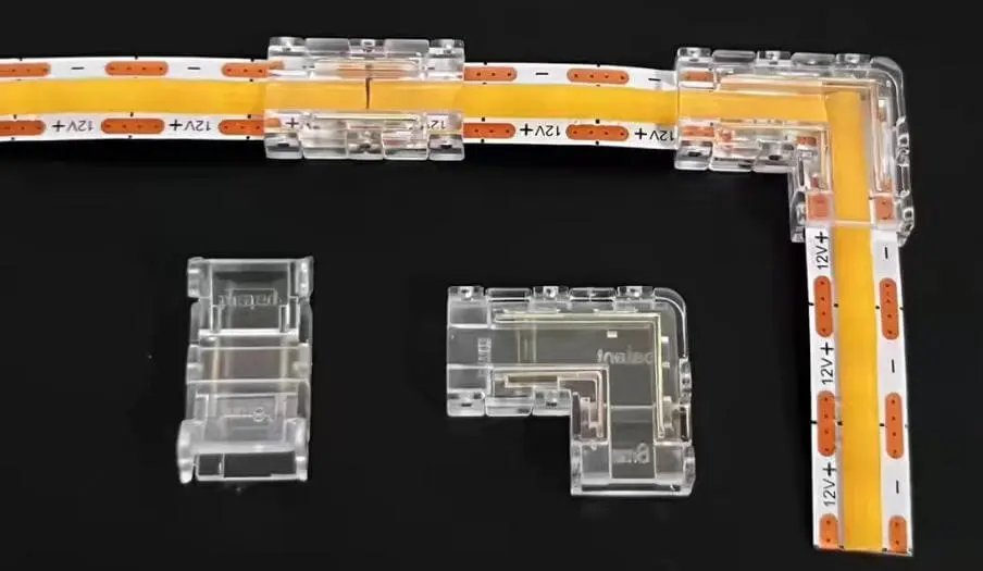
Ja, kundenspezifische vorkonfektionierte Kabelbäume, Stecker- und Spielverbindungen sowie vorgefertigte Streifensegmente reduzieren die Installationszeit vor Ort erheblich. Durch die Verlagerung des Lötens und der Steckermontage in die Fabrik eliminieren Sie Fehler im Feld, verbessern die Verbindungszuverlässigkeit und können die Installationsarbeitszeit bei großen Projekten um 30–50 % senken.
Der Fall für werkseitig gefertigte Verkabelung
Bei einem 200-Meter-Hotel-Cove-Beleuchtungsprojekt kann es 40 oder mehr Anschlussstellen geben — Streifen-zu-Streifen, Streifen-zu-Kabel, Kabel-zu-Netzteil. Wenn jeder Anschluss vor Ort 3–5 Minuten dauert (einschließlich Abisolieren, Löten, Schrumpfen und Testen), sind das 2–3 Stunden Arbeit nur für die Anschlüsse. Und jeder handgelötete Kontakt, der vor Ort oft in unbequemen Positionen mit schlechter Beleuchtung hergestellt wird, ist eine potenzielle Fehlerquelle.
Wenn wir kundenspezifische Kabelsätze in der Fabrik herstellen, wird jeder Anschluss auf einer Werkbank mit geeigneter Ausrüstung gelötet, unter Vergrößerung inspiziert und vor dem Versand getestet. Der Elektriker vor Ort steckt den Streifen einfach in den Kabelsatz und befestigt ihn. Die gesamte Anschlusszeit pro Punkt sinkt auf unter 30 Sekunden.
Arten von kundenspezifischen Steckverbindern
Es gibt mehrere Optionen, abhängig vom Projekt:
- Vorgelötete Pigtails — Kurze Kabelenden, die direkt im Werk an jedes Streifenstück gelötet sind. Der Installateur verbindet die Pigtails einfach mit dem Verteilungsdraht mittels Schnellanschlussklemmen oder Schraubklemmen.
- Plug-and-Play-Inline-Steckverbinder — Männliche/weibliche Steckverbinder, die vorinstalliert an Streifen- und Verteilungsleitungen angebracht sind. Diese lassen sich ohne Werkzeuge einrasten.
- Wasserdichte Steckverbinder — Für Außen- oder Nassbereichsprojekte (IP65/IP67/IP68) sorgen werkseitig versiegelte Steckverbinder für einen deutlich zuverlässigeren Schutz vor Feuchtigkeit als vor Ort aufgebrachte Silikone oder Schrumpfschläuche.
- Verteiler-Übergabeboxen — Vorgefertigte Boxen mit Anschlussklemmen oder Sicherungs-Ausgängen für jeden Bereich.
Lötverbindungen vs. Klemmenverbindungen
Klemmen (Schnapp-)Verbindungen sind praktisch für kleine Projekte und Prototypen, haben jedoch Grenzen. Sie können sich im Laufe der Zeit durch thermische Ausdehnung und Vibrationen lockern und erhöhen den Widerstand an der Verbindung. Für groß angelegte, dauerhafte Installationen sind gelötete Verbindungen der professionelle Standard.
Das gesagt, ist die beste Lösung eine werkseitig gelötete Verbindung mit einem werkzeugfreien Steckverbinder am anderen Ende. Dies bietet die Zuverlässigkeit des Lötens dort, wo es darauf ankommt, und die Geschwindigkeit eines Steckers, wo der Installateur es benötigt.
Wie man einen individuellen Kabelbaum plant
Wenn Sie mit einem Anbieter wie uns an einem OEM- oder Projektbasis arbeiten, benötigen wir folgende Informationen, um Ihr Verkabelungspaket zu erstellen:
- Grundrisszeichnung der Anlage mit Streifenpositionen und Längen
- Standort des Netzteils und Menge
- Spannung und Wattzahl von jedem Streifentyp
- IP-Bewertung Anforderungen pro Zone
- Standorte des Controllers/Dimmer und Signalart (PWM, DALI, DMX)
Mit diesen Informationen kann unser Engineering-Team ein vollständiges Verkabelungspaket entwerfen — einschließlich vorgefertigter Streifenabschnitte in der richtigen Länge, vorkonfektionierter Kabelbäume mit dem richtigen Querschnitt und der richtigen Länge, beschrifteter Steckverbinder für jede Zone und einem Verkabelungsdiagramm für den Installateur.
Der versteckte Vorteil: weniger Rückrufe
Neben der Zeitersparnis bei der Installation reduziert maßgeschneiderte Verkabelung auch Rückrufe. Lose Verbindungen, verpolte Anschlüsse und mismatched Drahtquerschnitte sind nach unserer Erfahrung die drei Hauptursachen für Serviceanrufe nach der Installation. Werkseitig gefertigte Kabelbäume eliminieren alle drei. Der Installateur folgt den Beschriftungen, steckt die Steckverbinder auf und schaltet ein. Wenn jede Verbindung vor Verlassen der Fabrik getestet wurde, sinken die Chancen auf einen Ausfall im Feld erheblich.
Für Auftragnehmer und Händler, die ihren Ruf auf Zuverlässigkeit aufbauen, rechnet sich dieser Ansatz schnell — nicht nur bei Arbeitszeitersparnissen, sondern auch bei reduzierten Garantieansprüchen und zufriedeneren Endkunden.
Fazit
Groß angelegte LED-Streifenprojekte scheitern oder bestehen bereits in der Planungsphase — nicht während der Installation. Berechnen Sie Ihre Lasten, wählen Sie die richtige Spannung, verdrahten Sie parallel, speisen Sie die Energie an den richtigen Stellen ein und berücksichtigen Sie kundenspezifische Kabelbäume, die Komplexität vom Einsatzort in die Fabrik verlagern.
Fußnoten
- Erklärt bewährte Verfahren für die Verkabelung von LED-Streifen, um häufige Probleme zu vermeiden. ↩︎
- Bietet Anleitungen zur Berechnung des Strombedarfs für LED-Streifeninstallationen. ↩︎
- Definiert Spannungsabfall und seine Auswirkungen auf die Leistung von LED-Streifen. ↩︎
- Erklärt das Konzept und die Vorteile von Parallelschaltungen für LED-Streifen. ↩︎
- Bietet eine vollständige Anleitung zur Stromeinspeisung für LED-Streifenbeleuchtungen. ↩︎
- Bietet eine umfassende Definition und Erklärung des American Wire Gauge von einer anerkannten Quelle. ↩︎
- Erläutert, wie der Kabelquerschnitt die Stromkapazität und den Spannungsabfall in LED-Systemen beeinflusst. ↩︎
- Vergleicht DMX- und DALI-Beleuchtungssteuerungsprotokolle für unterschiedliche Anwendungsbedürfnisse. ↩︎
- Beschreibt, wie Aluminiumprofile Schutz, Wärmeableitung und ein fertiges Erscheinungsbild für LED-Streifen bieten. ↩︎
- Erklärt die entscheidende Rolle des thermischen Managements für die Leistung und Lebensdauer von LEDs. ↩︎

 English
 Spanish
 German
 Russian
 Arabic
 French
 Portuguese