
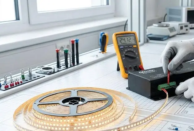
Wir sehen zurückgegebene LED-Streifen, die einwandfrei funktionierten—bis jemand sie an den falschen Controller anschloss oder eine grundlegende Spannungsprüfung übersprang.
Um LED-Streifenlichter mit einem Controller einzurichten und zu testen, müssen Sie zunächst den Streifentyp und die Spannung mit einem kompatiblen Controller und einer Stromversorgung abstimmen, die positiven und farbigen Anschlüsse korrekt anschließen, die Fernbedienung oder App koppeln und dann einen vollständigen Funktionstest durchführen, bevor sie dauerhaft montiert werden.
Der Prozess ist einfach, aber jeder Schritt birgt die Gefahr, dass etwas schiefgehen kann Spannungskonformität 1. Unten erläutere ich den Verkabelungs-, Test-, Fehlerbehebungs- und Synchronisationsprozess, den wir jedem Auftragnehmer und Großhändler empfehlen, der bei uns einkauft. Wenn Sie die Reihenfolge richtig einhalten, vermeiden Sie Rückrufe, verschwendete Streifen und frustrierte Kunden.
Wie verdrahte ich meine projektgerechten LED-Streifen korrekt an einen professionellen Controller?
Verwechslungsfehler bei der Verkabelung verursachen die meisten LED-Streifen-Ausfälle, die wir im Rahmen von Garantiefällen sehen—und fast alle sind mit einem klaren Prozess vermeidbar DMX512-Steuerungssystem 2.
Verbinden Sie Ihre LED-Streifen mit einem professionellen Controller, indem Sie die gekennzeichnete positive Fläche des Streifens mit dem V+-Anschluss des Controllers verbinden, dann jeden Farbkanal (R, G, B oder W) mit seinem entsprechenden Anschluss am Controller abgleichen und schließlich den Eingang des Controllers mit einer spannungsgleichen Stromversorgung verbinden.
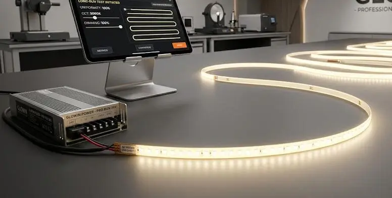
Kennen Sie Ihren Streifentyp, bevor Sie ein Kabel berühren
Nicht jeder LED-Streifen verwendet dasselbe Verkabelungsschema. Ein einfarbiger Streifen hat nur zwei Drähte: positiv und negativ. Ein RGB-Streifen 3 hat vier: V+, R, G und B. Ein RGBW-Streifen fügt einen fünften Draht für den dedizierten Weißkanal hinzu. Adressierbare Streifen 4 wie WS2812B verwenden ein völlig anderes Datenlinien-Protokoll.
Wenn Sie einen RGB-Streifen an einen Dimmer für Einfarbige anschließen, reagiert nur ein Kanal. Wenn Sie einen RGBW-Streifen 5 an einen RGB-Controller anschließen, verlieren Sie den Weißkanal vollständig. Die erste Regel ist einfach: Bestätigen Sie den Streifentyp, und wählen Sie dann den passenden Controller.
Lesen der gedruckten Labels auf dem Streifen
Unser Technikteam sagt den Kunden immer dasselbe: Vertrauen Sie den auf dem Streifen gedruckten Labels, nicht den Farben der Kabelisolierung. Wir haben gesehen, dass Installateure annehmen, dass ein rotes Kabel immer positiv ist oder dass die grüne Isolierung immer das grüne Signal trägt. Diese Annahme führt zu vertauschten Kanälen oder toten Streifen. Drehen Sie den Streifen um. Lesen Sie die Siebdrucke. Es wird etwas stehen wie V+, R, G, B. Diese Labels sind Ihre verlässliche Quelle.
Terminalverdrahtung Schritt für Schritt
Hier ist eine grundlegende Verdrahtungssequenz für eine RGB-Konfiguration:
| Schritt | Aktion | Detail |
|---|---|---|
| 1 | Schneiden Sie die Drahtenden ab | Bedecken Sie 5–7 mm blankes Kupfer; lassen Sie keine Isolierung im Terminal |
| 2 | Stecken Sie das V+-Draht in das V+-Terminal des Controllers | Ziehen Sie die Schraube fest an das blanke Kupfer |
| 3 | Stecken Sie den R-Draht in das R-Terminal des Controllers | Entsprechend der aufgedruckten R-Fläche des Streifens |
| 4 | Stecken Sie den G-Draht in das G-Terminal des Controllers | Entsprechend der aufgedruckten G-Fläche des Streifens |
| 5 | Stecken Sie den B-Draht in das B-Terminal des Controllers | Entsprechend der aufgedruckten B-Fläche des Streifens |
| 6 | Verbinden Sie das Stromversorgung 6 mit dem DC-Eingang des Controllers | Spannung anpassen: 12V-Streifen verwenden 12V-Stromversorgung, 24V-Streifen verwenden 24V-Stromversorgung |
| 7 | Polarisierung vor dem Einschalten doppelt überprüfen | Positiv zu positiv, negativ zu negativ |
Spannungsanpassung ist unverhandelbar
Wenn wir Musterkits an neue Partner in Deutschland oder Australien versenden, legen wir immer eine Erinnerungskarte bei: Überprüfen Sie die Spannung. Ein 12V-Streifen an einer 24V-Versorgung überhitzt und brennt schnell durch. Ein 24V-Streifen an einer 12V-Versorgung glüht kaum. Die Stromversorgung muss die exakte Nennspannung des Streifens liefern – keine Ausnahmen.
Steckverbinder vs. Löten
Für schnelle Prototypen oder temporäre Testaufbauten sind Steckverbinder in Ordnung. Aber für dauerhafte kommerzielle Installationen sind gelötete Verbindungen oder richtig angezogene Schraubklemmen weitaus zuverlässiger. Wir haben gesehen, dass Steckverbinder mit der Zeit locker werden Thermocycling 7, insbesondere in Deckenleisten, wo die Temperaturen schwanken. Für jedes Projekt, das jahrelang ohne Serviceeinsätze halten muss, sind Löt- oder Schraubklemmen die richtige Wahl.
Welche Schritte sollte ich befolgen, um die Farbkonsistenz und die Dimmstabilität meines Setups zu testen?
Auf unserer Qualitätskontrolllinie durchläuft jede Rolle vor dem Versand eine Prüfung der Farbkonsistenz. Sie sollten dasselbe vor Ort tun, bevor Sie sich für eine dauerhafte Installation entscheiden.
Nach der Verkabelung schalten Sie den Streifen ein und testen jeden Farbkanal einzeln bei voller Helligkeit, dann bei 25%, 50% und 75% Helligkeit. Prüfen Sie auf gleichmäßige Farbe über die gesamte Länge, sanfte Dimmübergänge und das Fehlen von Flimmern bei niedriger Helligkeit, um einen stabilen Betrieb zu bestätigen.
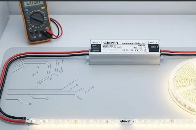
Warum vor der Montage testen
Selbstklebende LED-Streifen sind nach der Montage im Wesentlichen Einwegprodukte. Wenn Sie einen Streifen auf ein Aluminiumprofil kleben, über eine 10 Meter lange Deckenleiste führen und dann feststellen, dass sich die Farben am Ende verschieben, stehen Sie vor einem kostspieligen Rückbau. Das Testen auf einer Werkbank dauert fünf Minuten. Nacharbeiten dauert Stunden.
Der Farbkanal-Test
Schalten Sie jeden Kanal – Rot, Grün, Blau – einzeln ein. Achten Sie auf gleichmäßige Helligkeit von der ersten bis zur letzten LED. Wenn der rote Kanal in der Nähe des Controllers hell ist, aber am Ende verblasst, haben Sie wahrscheinlich ein Spannungsabfall 8 Problem. Wenn der grüne Kanal überhaupt nicht leuchtet, überprüfen Sie diesen Anschluss erneut. Dieser Einzelkanal-Test isoliert Verdrahtungsfehler schnell.
Der Dimmstabilitätstest
Nicht alle Controller dimmen sanft. Einige verwenden Pulsweitenmodulation (PWM) 9 bei Frequenzen, die für das menschliche Auge zu niedrig sind, was sichtbares Flimmern verursacht – insbesondere auf Kamera. Hier ist, wie wir testen empfehlen:
| Dimmstufe | Worauf zu achten ist | Bestehen-Kriterium |
|---|---|---|
| 100% | Volle Helligkeit, gleichmäßige Farbe | Keine Hotspots, keine ausgefallenen LEDs |
| 75% | Leichte Reduzierung | Sanfter Übergang, kein Farbverschiebung |
| 50% | Mittlere Helligkeit | Kein sichtbares Flimmern, gleichmäßiger Ausgang |
| 25% | Niedrige Helligkeit | Kein Flimmern, kein Summen vom Treiber |
| 5–10% | Sehr gering | Sanfter Fade, LEDs bleiben ohne Ruckeln an |
Wenn Sie bei niedrigen Dimmstufen Flimmern bemerken, ist die PWM-Frequenz Ihres Controllers möglicherweise zu niedrig. Viele professionelle Controller arbeiten bei 1 kHz oder höher, was sichtbares Flimmern eliminiert. Budget-Controller laufen manchmal bei 200–500 Hz, und dort beginnen die Probleme—besonders in Gastronomie- oder Einzelhandelsumgebungen, in denen Kunden Inhalte mit Smartphones filmen.
Weißabgleich und Farbtemperatur
Für RGBW- oder tunable-white-Streifen testen Sie die weiße Ausgabe bei mehreren Farbtemperaturen. Gehen Sie entlang des Streifens und suchen Sie nach Farbverschiebungen—manchmal driftet das warme Ende des Streifens leicht rosa oder grün im Vergleich zum kühlen Ende. Dies ist oft ein Bin-Konsistenzproblem auf LED-Ebene, weshalb wir unsere LEDs in enge MacAdam-Schritt-Bins 10 vor der Montage sortieren. Wenn Sie Inkonsistenzen feststellen, muss der Streifen möglicherweise durch eine Charge mit engeren Bins ersetzt werden.
Modus- und Szenentests
Wechseln Sie durch mehrere voreingestellte Modi am Controller: statische Farbe, Farbverlauf, Farbwechsel und beliebige benutzerdefinierte Szenen. Bestätigen Sie, dass die Übergänge fließend sind und dass der Streifen innerhalb einer Sekunde auf jeden Befehl reagiert. Verzögerte Reaktionen können auf ein Firmware-Problem des Controllers oder eine überlastete Datenleitung bei adressierbaren Streifen hinweisen.
Dokumentieren Sie Ihre Ergebnisse
Für gewerbliche Projekte führen Sie ein einfaches Protokoll Ihrer Testergebnisse. Notieren Sie das Datum, die Chargennummer des Streifens, das Modell des Controllers, das Modell der Stromversorgung und den Bestehen-/Durchfall-Status für jeden Test. Diese Dokumentation ist hilfreich, falls Sie einen Garantieanspruch geltend machen müssen oder ein Kunde einen Nachweis über die Inbetriebnahme verlangt.
Wie kann ich Signalstörungen oder Spannungsabfälle während meines ersten Tests beheben?
Wenn wir in unserem Ausstellungsraum Langstreifen-Demos durchführen—manchmal 20 Meter oder mehr—ist Spannungsabfall der erste Fehler, der auftritt. Signalstörungen folgen direkt danach, insbesondere in Gebäuden voller anderer elektronischer Geräte.
Beheben Sie Spannungsabfall, indem Sie die Spannung am entfernten Ende des Streifens mit einem Multimeter messen; eine Messung, die mehr als 0,5 V unter der Nennspannung liegt, zeigt die Notwendigkeit für Parallelschaltung, dickere Kabelquerschnitte oder einen Verstärker an. Für Signalstörungen schützen Sie Datenkabel und trennen Sie sie von Hochspannungs-AC-Leitungen.
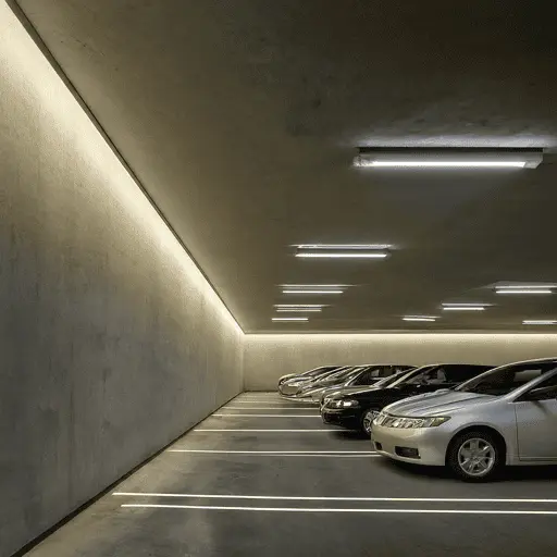
Verstehen des Spannungsabfalls
Spannungsabfall tritt auf, weil Kupferdraht Widerstand hat. Je länger die Leitung und je dünner der Leiter, desto mehr Spannung verlieren Sie zwischen Netzteil und dem entfernten Ende des Streifens. Bei einem 12V-Streifen bedeutet ein Abfall von 1V eine Reduktion der verfügbaren Spannung um 8%. Das führt zu dunkleren LEDs, verschobener Farbtemperatur und sichtbaren Helligkeitsverläufen entlang des Streifens.
So messen Sie den Spannungsabfall
Holen Sie sich ein einfaches Multimeter. Stellen Sie es auf Gleichspannung (DC). Messen Sie am Netzeingang des Streifens—Sie sollten nahe bei 12V oder 24V liegen. Messen Sie dann am entfernten Ende. Wenn der Unterschied mehr als 0,5V beträgt, müssen Sie Maßnahmen ergreifen.
| Symptom | Wahrscheinliche Ursache | Lösung |
|---|---|---|
| Streifen wird zum entfernten Ende hin dunkler | Spannungsabfall bei langem Lauf | Verwenden Sie Parallelschaltung oder speisen Sie von beiden Enden ein |
| Farben verschieben sich von Weiß zu Warmweiß am entfernten Ende | Unzureichende Spannung für blaue LEDs | Verwenden Sie dickere Kabelquerschnitte (z. B. 18 AWG statt 22 AWG) |
| Streifen flackert nur am entfernten Ende | Grenzwertiger Spannungsabfall löst intermittierenden LED-Betrieb aus | Fügen Sie einen LED-Verstärker in der Mitte hinzu |
| Der gesamte Streifen ist dunkel | Netzteil ist für die Gesamtbelastung des Streifens zu klein dimensioniert | Berechnen Sie die Gesamtleistung und rüsten Sie das Netzteil mit 20% Spielraum auf |
| Zufällige Farbfehler bei adressierbaren Streifen | Signalverschlechterung über die Entfernung | Verwenden Sie einen Signalverstärker oder kürzere Datenleitungen |
Parallele Verkabelung vs. Serienschaltung
Die meisten LED-Streifen sind intern in einer kontinuierlichen Serie verdrahtet. Wenn Sie die Länge erhöhen, steigt der Widerstand. Die Lösung besteht darin, die Stromversorgung von mehreren Punkten zu speisen—dies nennt man parallele Strominjektion. Führen Sie ein separates Paar Stromkabel vom Netzteil zum Mittelpunkt und zum entfernten Ende des Streifens. Dadurch bleibt die Spannung entlang der gesamten Strecke konstant. In unserer Fabrik markieren wir bei Sonderanfertigungen, die länger als 10 Meter sind, die Injektionspunkte vor.
Signalstörungen bei adressierbaren Streifen
Adressierbare LED-Streifen—wie WS2812B oder SK6812—verwenden eine digitale Datenleitung. Dieses Datensignal ist anfällig für elektromagnetische Störungen (EMI) durch nahegelegene Wechselstromleitungen, Motoren oder Schaltnetzteile. Symptome sind zufälliges Flackern, falsche Farben oder Bereiche des Streifens, die nicht reagieren.
Um Störungen zu reduzieren, halten Sie die Datenleitung physisch mindestens 15 cm von Wechselstromkabeln entfernt. Verwenden Sie geschirmtes Kabel für lange Datenleitungen. Fügen Sie einen 220–470 Ohm Widerstand in die Datenleitung am Controller-Ausgang ein. Platzieren Sie einen 1000 µF Kondensator über die Stromversorgung des ersten LEDs, um Spannungsspitzen zu absorbieren.
Wann man einen Verstärker verwenden sollte
Ein LED-Verstärker wiederholt das Signal des Controllers und versorgt den nächsten Streifenabschnitt mit frischer Energie. Dies ist bei Streifen notwendig, die über die vom Controller angegebene maximale Ausgangsleistung hinausgehen. Wenn Ihr Controller beispielsweise 10 Ampere bewältigt, Ihr gesamter Streifen jedoch 15 Ampere zieht, benötigen Sie einen Verstärker für den Überschuss. Der Verstärker übernimmt das PWM-Signal vom Controller und treibt den zusätzlichen Streifenabschnitt von seiner eigenen Stromversorgung aus an.
Praktischer Feldtipp
Hier ist eine Erkenntnis, die wir von einem Auftragnehmer in Berlin gewonnen haben, der bei einer 15-Meter-RGBW-Installation immer wieder Flackern beobachtete. Er hatte für die gesamte Strecke 22 AWG Kabel verwendet. Der Wechsel auf 18 AWG und das Hinzufügen einer Strominjektion bei der 8-Meter-Marke haben das Problem vollständig beseitigt. Dickere Kabel und kürzere Stromleitungen lösen die meisten Spannungsabfallprobleme, ohne die Komplexität zu erhöhen.
Wie synchronisiere ich mehrere Controller, um eine einheitliche Beleuchtung in meiner gesamten gewerblichen Installation zu gewährleisten?
Eine der häufigsten Fragen, die wir von unseren Vertriebspartnern erhalten—insbesondere bei großen Hotel-Lobbys oder Einzelhandelsinstallationen—ist, wie man 50 Meter Streifenlicht wie eine einzige nahtlose Linie aussehen lässt, obwohl es tatsächlich von drei oder vier separaten Controllern gesteuert wird.
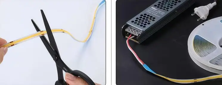
Synchronisieren Sie mehrere LED-Controller durch eine Master-Slave-Konfiguration, ein DMX512-Steuerungssystem oder eine zentrale Wi-Fi/Zigbee-Zentrale, die einheitliche Befehle an alle Controller gleichzeitig sendet, um eine identische Farbe, Helligkeit und Timing in allen Zonen Ihrer Installation zu gewährleisten.
Warum Synchronisation wichtig ist
In einem privaten Umfeld fallen kleine Unterschiede zwischen zwei Streifen möglicherweise nicht auf. Bei einer gewerblichen Installation—wie einer Deckenverzierung in einem Restaurant, einem Hotelkorridor oder einer Verkaufswand—sind Abweichungen in Farbe oder Timing sofort sichtbar. Kunden bemerken, wenn ein Abschnitt leicht blauer ist als der nächste oder wenn ein Farbverlauf eine halbe Sekunde zu spät beginnt. Synchronisation ist für professionelle Arbeiten unerlässlich.
Master-Slave-Konfiguration
Viele professionelle LED-Controller unterstützen einen Master-Slave-Modus. Ein Controller fungiert als Master und sendet sein Signal an einen oder mehrere Slave-Controller über eine Kabelverbindung (oft eine einfache Zweidraht- oder RJ45-Verbindung). Alle Slaves spiegeln die Ausgabe des Masters in Echtzeit wider. Dies ist die einfachste Synchronisierungsmethode und funktioniert gut für Installationen mit weniger als fünf oder sechs Zonen.
DMX512 Steuerung
Für größere oder komplexere Projekte ist DMX512 der Branchenstandard. Jeder Controller erhält eine DMX-Adresse und reagiert auf Befehle von einer zentralen DMX-Konsole oder Software. DMX unterstützt bis zu 512 Kanäle auf einem einzigen Universum, was für die meisten LED-Streifenprojekte mehr als ausreichend ist. Der Vorteil von DMX ist Präzision: Sie können jeden Controller individuell ansprechen und komplexe Szenen, Fade- und Zeitabläufe programmieren.
Drahtlose Synchronisation
Einige moderne Controller verwenden Wi-Fi, Zigbee oder Bluetooth-Mesh, um ohne Verkabelung zwischen den Einheiten zu synchronisieren. Eine zentrale App oder ein Hub sendet Befehle an alle Controller gleichzeitig. Dies funktioniert gut für Nachrüstprojekte, bei denen das Verlegen zusätzlicher Steuerdrähte unpraktisch ist. Drahtlose Systeme können jedoch eine leichte Latenz einführen—typischerweise 50–200 ms—was bei schnellen Farbwechseln bemerkbar sein kann.
Auswahl der richtigen Methode
| Methode | Am besten geeignet für | Vorteile | Nachteile |
|---|---|---|---|
| Master-Slave (verkabelt) | Kleine bis mittlere Installationen, 2–6 Zonen | Einfache Einrichtung, zuverlässig, keine Latenz | Erfordert physische Verkabelung zwischen den Controllern |
| DMX512 | Große gewerbliche Installationen, komplexe Szenen | Branchenstandard, präzise, skalierbar | Erfordert DMX-Konsole oder Software, höhere Kosten |
| Wi-Fi / Zigbee Mesh | Nachrüstungen, verteilte Zonen | Keine Inter-Controller-Verkabelung, App-Steuerung | Mögliche Latenz, abhängig von der Netzstabilität |
| RF-Fernbedienung (Gruppiert) | Budget-Installationen, einfache Synchronisation | Günstig, kein Netzwerk erforderlich | Begrenzte Szenensteuerung, weniger präzises Timing |
Sicherstellung einer einheitlichen Farbe über alle Zonen
Selbst bei perfekter Synchronisation können bei LED-Streifen aus verschiedenen Produktionschargen leichte Farbunterschiede auftreten. Deshalb sortieren und bündeln wir unsere LEDs sorgfältig und empfehlen Auftragnehmern, alle Streifen für ein Projekt in einer einzigen Charge zu bestellen. Wenn wir Bestellungen für Mehrzonenprojekte vorbereiten, ziehen wir Rollen aus derselben Produktionsserie und fügen Chargenrückverfolgbarkeitsdokumente bei, damit der Installateur die Konsistenz vor Ort überprüfen kann.
Praktische Inbetriebnahme-Tipps
Beginnen Sie damit, einen Controller zu programmieren und ihn gegen die Designabsicht zu überprüfen. Dann übertragen Sie diese Einstellungen auf alle anderen Controller. Führen Sie jede Szene im Beleuchtungsplan des Projekts aus und gehen Sie die gesamte Installation ab, um Unstimmigkeiten zu erkennen. Verwenden Sie ein Farbmessgerät, wenn die Projektvorgaben eine quantifizierte Gleichmäßigkeit erfordern. Speichern Sie schließlich die Konfiguration auf dem Master-Controller oder der DMX-Konsole, damit sie wiederhergestellt werden kann, falls ein Controller ersetzt werden muss.
Firmware- und Protokollkompatibilität
Stellen Sie sicher, dass alle Controller im Projekt die gleiche Firmware-Version verwenden und dass das gleiche Kommunikationsprotokoll genutzt wird. Das Mischen von Controller-Modellen oder Firmware-Versionen ist eine häufige Ursache für Synchronisationsfehler. Wenn wir Mehr-Controller-Sets liefern, flashen wir alle Einheiten vor dem Versand mit identischer Firmware, um diese Variable zu eliminieren.
Fazit
Richten Sie die Verkabelung zuerst richtig ein, testen Sie dann jede Funktion, bevor alles dauerhaft montiert wird. Stimmen Sie Ihre Spannung ab, lesen Sie die aufgedruckten Labels und überprüfen Sie jeden Farbkanal. Diese Reihenfolge—Bestätigen, Verbinden, Testen, Installieren—verhindert die meisten LED-Streifen-Ausfälle, die wir weltweit in Projekten beobachten.
Fußnoten
- Betont die entscheidende Bedeutung, die Spannung des LED-Streifens an das Netzteil anzupassen. ↩︎
- Erklärt DMX512 als ein standardisiertes digitales Kommunikationsnetzwerk zur Steuerung von Beleuchtung und Effekten. ↩︎
- Definiert RGB-LED-Streifen und wie sie Farben durch rote, grüne und blaue LEDs erzeugen. ↩︎
- Found a working Wikipedia page section explaining addressable RGB LED strips. ↩︎
- Erklärt RGBW-LED-Streifen, wobei die zusätzliche weiße LED für reineres Weißlicht sorgt. ↩︎
- Erklärt die Rolle, die Arten und die Auswahl von Netzteilen für LED-Streifen. ↩︎
- Hat eine funktionierende Wikipedia-Seite gefunden, die thermisches Zyklisieren erklärt. ↩︎
- Definiert Spannungsabfall als die Abnahme des elektrischen Potenzials entlang eines Leiters aufgrund von Widerstand. ↩︎
- Hat eine funktionierende Wikipedia-Seite gefunden, die Pulsweitenmodulation (PWM) erklärt. ↩︎
- Erklärt MacAdam-Ellipsen und Schritte als Maß für den Farbunterschied bei LEDs zur Konsistenz. ↩︎


 English
 Spanish
 German
 Russian
 Arabic
 French
 Portuguese