Most people focus on the light-emitting surface of a COB LED strip, but the real secret to longevity hides underneath polyimide-based flexible printed circuit boards 1. The flexible substrate is where performance lives or dies.
COB LED strip flexible substrates are primarily built on polyimide-based flexible printed circuit boards (FPC/FPCB) with copper foil conductors, coverlay insulation layers, adhesive backing, and a phosphor-silicone encapsulation on top. This layered material system determines the strip's flexibility, heat dissipation, electrical performance, and light uniformity.
On our production lines, we see firsthand how substrate quality separates a five-year installation from a one-year failure copper foil conductors 2. Below, we break down every layer, every material choice, and every structural decision that matters for project-grade COB LED strips.
How do I choose between single-sided and double-sided FPC for my project-grade COB LED strips?
This question comes up often when our engineering team reviews specifications with contractors and wholesalers coverlay insulation layers 3. The answer is not as simple as picking the cheaper option.
For most project-grade COB LED strips, double-sided FPC is the better choice because it provides wider copper traces, better current distribution, and improved heat dissipation. Single-sided FPC works for short runs and lower-power applications, but it struggles with voltage drop and thermal load in demanding commercial installations.
What Is FPC in a COB LED Strip?
FPC stands for Flexible Printed Circuit 4. It is the bendable circuit board that carries all the electrical traces and supports the LED chips. Think of it as the backbone of the strip. Without it, the LEDs have no power path and no physical support glass transition temperature (Tg) 5.
A single-sided FPC has copper traces on one side of the polyimide base film. A double-sided FPC has copper traces on both sides, connected by tiny plated-through holes called vias 6. This difference sounds small, but it changes everything about how the strip handles current and heat.
Why Double-Sided FPC Matters for Long Runs
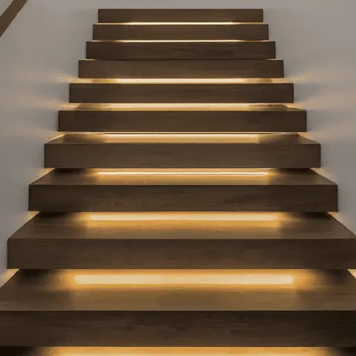
When we test strips for long-run commercial projects — say 10 meters or more — the voltage drop 7 on a single-sided FPC becomes visible. The LEDs at the far end look dimmer. The color temperature shifts. This is a deal-breaker for lighting designers who need uniform output across a cove or a display wall.
Double-sided FPC solves this by offering a return path on the bottom layer. The current flows more evenly. The resistance drops. The strip stays consistent from end to end.
Quick Comparison: Single-Sided vs. Double-Sided FPC
| Feature | Single-Sided FPC | Double-Sided FPC |
|---|---|---|
| Copper layers | 1 | 2 |
| Typical copper weight | 1 oz (35 µm) | 1–2 oz per side (35–70 µm) |
| Voltage drop on 5 m run | Noticeable | Minimal |
| Heat dissipation | Moderate | Better |
| Flexibility | Slightly more flexible | Slightly stiffer but still bendable |
| Cost | Lower | Higher |
| Best use case | Short runs, low power | Long runs, high power, commercial projects |
When Single-Sided FPC Is Enough
Not every job needs double-sided FPC. If you are installing a 2-meter accent strip inside a cabinet, a well-made single-sided board with 1-oz copper is perfectly fine. The run is short. The power draw is low. The cost savings make sense.
The key is to match the substrate to the project. Our advice to buyers in Australia and Germany is straightforward: tell us the run length, the wattage per meter, and the expected ambient temperature. We will recommend the right FPC structure.
Will the copper thickness in my flexible substrate affect the long-term color consistency of my installation?
We had a client in Melbourne who came to us after replacing an entire hotel corridor of LED strips within 18 months. The original supplier used a very thin copper layer. The strips looked fine at first, but color shifted noticeably over time.
Yes, copper thickness directly affects long-term color consistency. Thinner copper increases electrical resistance, which causes voltage drop along the strip. This voltage drop changes the current flowing through each LED, leading to visible color temperature shifts and brightness variations over the life of the installation.
How Copper Thickness Relates to Voltage Drop
Copper is the highway for electricity inside your LED strip. A narrow, thin highway causes traffic jams. In electrical terms, thinner copper means higher resistance. Higher resistance means more energy is lost as heat rather than reaching the LEDs at the far end. The LEDs at the end receive less current, so they emit a different color temperature.
This is not theoretical. We measure it every day during quality control. A strip with 0.5-oz copper behaves very differently from one with 2-oz copper on a 10-meter run.
Copper Weight Options and Their Real-World Impact
| Copper Weight | Thickness (µm) | Resistance per Meter (relative) | Best Application | Color Stability on Long Runs |
|---|---|---|---|---|
| 0.5 oz | ~17 µm | High | Budget products, very short runs | Poor |
| 1 oz | ~35 µm | Moderate | Standard residential projects | Acceptable for runs under 5 m |
| 2 oz | ~70 µm | Low | Commercial and project-grade | Good for runs up to 10 m |
| 3 oz | ~105 µm | Very low | High-power, extended runs | Excellent |
The Hidden Cost of Thin Copper
Some factories cut costs by using 0.5-oz copper or even thinner. The strip works out of the box. It passes a quick visual check. But three months into a commercial installation, the problems start. The end of the strip looks warmer or cooler than the beginning. The client complains. The contractor has to re-do the work.
Our production team defaults to 2-oz copper for any strip going into a project environment. The cost difference is small compared to the labor cost of a callback.
What About Rolled Copper vs. Electrodeposited Copper?
This is a detail most buyers never ask about, but it matters. Rolled annealed (RA) copper 8 has a smoother grain structure. It survives repeated bending much better than electrodeposited (ED) copper 9. For flexible COB strips that need to wrap around curves, RA copper keeps the circuit intact longer.
ED copper is cheaper and works fine for strips mounted flat on a surface. But if the strip will be bent during installation, RA copper is worth the premium.
Thermal Effects of Copper Thickness
Thicker copper does not just carry more current. It also spreads heat better. LED chips generate heat at the junction. That heat needs to travel away from the chip and into the surrounding environment. A thicker copper layer acts as a wider heat-spreading plane. This keeps the LED junction temperature lower, which directly improves the lifespan and color stability of the phosphor coating.
How can I verify that the substrate materials meet the strict heat dissipation standards for my commercial projects?
When we ship samples to distributors in Germany, the first question is rarely about brightness. It is about thermal performance. European project specifications are strict, and rightfully so. Heat is the number one killer of LED longevity.
You can verify substrate heat dissipation performance by requesting material datasheets for the polyimide base film and copper weight, conducting thermal imaging tests under full load, checking UL or IEC certifications, and asking the manufacturer for thermal resistance measurements of the complete FPC stack-up.
Start with the Material Datasheets
Every reputable FPC material has a published datasheet. The polyimide film should list its thermal conductivity 10, glass transition temperature (Tg), and continuous operating temperature rating. For LED strip applications, you want a polyimide with a Tg above 250°C and continuous temperature tolerance of at least 200°C.
Ask the strip manufacturer which polyimide brand they use. Names like DuPont Kapton and SKC Kolon are widely recognized. If a factory cannot tell you what base film they use, that is a red flag.
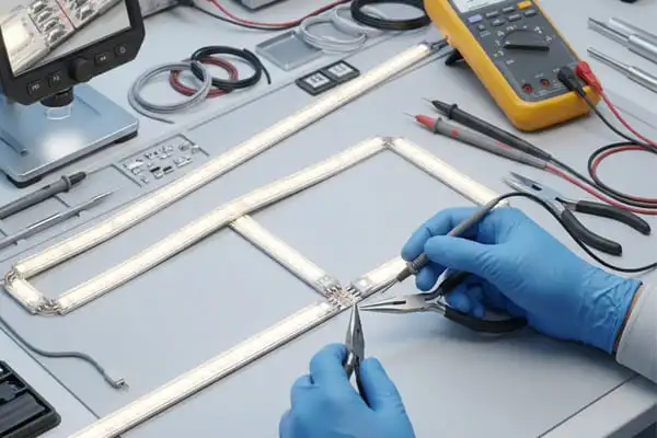
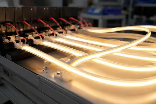
Thermal Imaging Under Load
The most practical test is simple. Power the strip at full rated wattage in a controlled environment for at least two hours. Then use a thermal imaging camera to check temperature distribution along the strip. Look for hot spots. Look for temperature differences between the beginning and the end.
On our production line, we perform this test on every batch. A well-designed substrate should keep the maximum surface temperature below 60°C at rated power in a 25°C ambient environment, assuming proper mounting on an aluminum profile.
Key Thermal Specifications to Request
| Specification | What It Tells You | Target for Project-Grade Strips |
|---|---|---|
| Polyimide Tg | Maximum temperature before material softens | > 250°C |
| Copper weight | Heat spreading ability | ≥ 1 oz, ideally 2 oz |
| Thermal conductivity of substrate | How fast heat moves through the base | ≥ 0.2 W/m·K for polyimide |
| FPC total thickness | Affects flexibility and thermal mass | 0.2–0.4 mm typical |
| Maximum operating temperature | Safety limit for continuous use | Rated ≥ 105°C |
| UL 94 flammability rating | Fire resistance classification | V-0 preferred |
Certifications Matter
For commercial projects, especially in Australia and Germany, you need documented proof. UL recognition on the FPC materials gives you a baseline of safety. IEC 60598 compliance covers the complete luminaire system. In our experience, distributors who skip the certification check end up with warranty headaches later.
We always provide third-party test reports with our shipments. If a supplier resists sharing these, walk away.
Advanced Thermal Solutions on the Horizon
Some research labs are exploring graphene-enhanced polyimide and boron nitride composite substrates. These materials can dramatically improve localized heat spreading without adding rigidity. They are not mainstream yet, but we keep our eye on them for future product development. For now, properly specified polyimide with adequate copper weight and good thermal interface to an aluminum channel remains the proven approach.
Can I request a customized substrate structure to handle the voltage drop issues in my long-run COB lighting designs?
This is one of the most common engineering discussions we have with project buyers. A 20-meter continuous run without visible brightness change is not easy. Standard off-the-shelf strips often fail this test. The good news is that customization is absolutely possible.
Yes, you can request a customized substrate structure. Options include wider FPC boards, thicker copper layers, double-sided copper with optimized via patterns, and segmented power injection points designed into the circuit layout. A good manufacturer will co-develop the substrate design with you to meet specific voltage drop targets for your run length.
Why Standard Substrates Fail on Long Runs
A standard COB strip might use a 10 mm wide, 1-oz single-sided FPC. That works for a 3-meter under-cabinet light. But stretch it to 15 or 20 meters, and the voltage at the far end drops below the threshold for consistent LED output. The result is visible dimming and color shift.
The physics is simple. Resistance increases with length and decreases with cross-sectional area. To reduce voltage drop, you need wider traces, thicker copper, or more copper layers.
Customization Options We Offer
Here is what we typically discuss with buyers who face long-run challenges:
Wider FPC boards. Going from 10 mm to 12 mm or even 15 mm gives the copper traces more room. Wider traces mean lower resistance.
Heavier copper. Upgrading from 1-oz to 2-oz or 3-oz copper cuts resistance roughly in half or more. This is the single most impactful change.
Double-sided copper with via stitching. Using both sides of the FPC doubles the available copper cross-section. Vias connect the top and bottom layers, creating a unified conductive path.
Power injection points. We can design the circuit layout so that power can be fed at multiple points along the run. This shortens the effective electrical distance and dramatically reduces end-to-end voltage drop.
Segmented constant-current design. Instead of a single long constant-voltage run, the strip can be broken into constant-current segments that self-regulate brightness regardless of input voltage variations.
The Co-Development Process
When a distributor or contractor comes to us with a specific project, we follow a clear process. First, we review the run length, power requirements, and installation environment. Then, our engineers simulate the voltage drop using the proposed substrate parameters. We share the results and suggest modifications. Once approved, we produce samples for testing.
This co-development approach is exactly what sets project-grade suppliers apart from commodity sellers. It costs a bit more time upfront, but it eliminates expensive failures in the field.
Understanding the Phosphor-Silicone Encapsulation Layer
While the copper and polyimide layers handle electricity and heat, the top layer of a COB strip also plays a structural role. The phosphor-silicone encapsulation is a continuous coating over the bare LED chips. It converts blue LED light into the desired white color temperature and creates the signature smooth, dot-free light output.
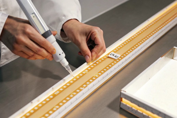
This silicone layer must remain flexible, heat-resistant, and optically stable. A poor-quality phosphor mix degrades under heat, causing the strip to yellow over time. When we select phosphor-silicone materials, we test for color stability after 3,000 hours of accelerated aging. This ensures the visual quality matches the electrical reliability built into the substrate below.
The Full COB LED Strip Layer Stack-Up
For a complete picture, here is the full material stack from bottom to top:
- Adhesive backing — 3M or equivalent double-sided tape for mounting.
- Polyimide base film — The structural foundation, typically 25–50 µm thick.
- Copper circuit layer(s) — Etched traces for power distribution, 1–3 oz.
- Coverlay insulation — Polyimide or solder mask protecting the copper.
- LED chips — Bare dies mounted directly on the board (chip-on-board).
- Phosphor-silicone encapsulation — Continuous layer for light conversion and uniformity.
Every layer interacts with the others. A change in copper weight affects heat, which affects the phosphor layer above. A change in polyimide thickness affects flexibility, which affects how the strip conforms to curved surfaces. This is why substrate engineering is not a one-layer decision — it is a system design.
Conclusion
The substrate is the foundation of every COB LED strip. Choosing the right polyimide, copper weight, FPC structure, and encapsulation determines whether your installation lasts years or months. Ask the right questions, request the right data, and partner with a manufacturer who understands substrate engineering from the inside out.
Footnotes
- Explains the primary material for flexible substrates. ↩︎
- Details the conductive material in FPCBs. ↩︎
- Describes the insulating layer in FPCBs. ↩︎
- Defines the core technology of the substrate. ↩︎
- Important thermal property of polyimide. ↩︎
- Explains how layers are connected in double-sided FPC. ↩︎
- Explains a critical electrical performance issue. ↩︎
- Differentiates copper types for flexibility. ↩︎
- Contrasts with RA copper for flexibility. ↩︎
- Key property for heat dissipation in polyimide. ↩︎