Over the years on production line, we have seen hundreds of lighting projects ruined by one simple problem: visible hotspots. Contractors calls frustrated. Designers send photos of dotted reflections on glossy countertops. The root cause is almost always the same — the LED strip they used was not dense enough to produce a continuous line of light. That single flaw can downgrade an entire high-end fit-out from elegant to cheap-looking.
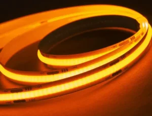
COB LED strip lights achieve uniform, spotless light output by mounting hundreds of tiny LED chips directly onto the circuit board in an extremely tight arrangement, then covering them with a continuous phosphor layer that blends individual emissions into one seamless, dot-free line of light.
The secret is not a fancy diffuser cover. It is chip density 1, phosphor uniformity, wide beam angles, and stable current delivery all working together. Below, we break down each factor so you can specify, source, and install COB strips with full confidence in the result.
Why should I choose COB technology over traditional SMD strips for my high-end architectural projects?
When our engineering team first started developing COB strips for export to Germany and Australia, the difference in visual quality was immediately obvious on the test bench. If your project includes any reflective surface — glass, marble, stainless steel — the choice matters even more.
You should choose COB technology because it eliminates visible hotspots, produces a continuous line of light, offers superior color uniformity, and delivers a premium aesthetic that traditional SMD strips simply cannot match on reflective or close-view surfaces.

The Core Difference: Chip Packaging
Traditional SMD strips 2 use individually packaged LED components soldered onto the flexible circuit board at regular intervals. Common spacings are 60, 120, or even 168 LEDs per meter. Even at 168 LEDs per meter, there is a visible gap between each light point. When those strips sit behind a frosted channel, the dots blur out somewhat. But on shallow profiles, reflective ceilings, or direct-view applications, the dots remain visible.
COB — Chip on Board 3 — takes a fundamentally different approach. Instead of placing individually packaged LEDs, we mount bare LED chips 4 directly onto the FPCB. Then we coat the entire array with one continuous layer of phosphor-infused silicone. The result is a flat, even surface that glows as a single unit. No individual points. No gaps.
Visual Impact on Reflective Surfaces
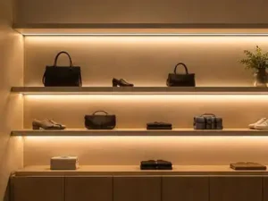
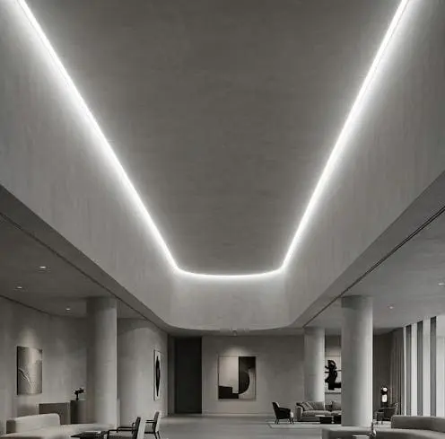
High-end architectural projects often feature polished stone, glass splashbacks, and lacquered cabinetry. These surfaces act like mirrors. Any light strip with visible dots will project a row of bright circles onto those surfaces. We have seen this ruin kitchen installations and hotel lobby details. COB strips solve this because the light source itself is already continuous before it even hits a diffuser.
Side-by-Side Comparison
| Feature | Traditional SMD Strip | COB LED Strip |
|---|---|---|
| Chip packaging | Individual LED packages soldered at intervals | Bare chips mounted directly on FPCB 5 |
| Typical density | 60–168 LEDs/m | 320–480+ chips/m |
| Visible hotspots | Yes, especially at close range | No, continuous light line |
| Beam angle | 120° typical | Up to 180° |
| Diffuser dependency | High — needs deep channel to hide dots | Low — looks smooth even without diffuser |
| Ideal use case | Concealed accent lighting | Visible, close-view, reflective surface lighting |
When SMD Still Works Fine
To be fair, not every project needs COB. If the strip is hidden inside a deep aluminum channel with a heavy frosted diffuser and the viewing distance is more than one meter, a high-density SMD strip can look perfectly acceptable. COB becomes essential when the strip is in a shallow profile, at eye level, or reflected on glossy materials.
Cost Consideration
COB strips do cost more per meter than standard SMD strips. But the premium buys you optical refinement, not just raw lumens. For high-end architectural projects — the kind where a lighting designer's reputation is on the line — that refinement is not optional. It is the baseline expectation.
How can I eliminate visible hotspots in my shallow profile installations using COB LED strips?
Shallow profiles are one of the trickiest challenges we encounter when supporting contractors in Australia and Germany. The gap between the LED strip and the diffuser cover is so small that even minor light irregularities become visible.
To eliminate hotspots in shallow profiles, select COB strips with a density of at least 480 chips per meter, ensure the phosphor coating is factory-verified for thickness uniformity, and pair the strip with a slim opal diffuser to further smooth out any residual variation.

Why Shallow Profiles Expose Every Flaw
In a standard aluminum channel, the diffuser sits 8–12 mm above the strip. That distance gives light room to spread and overlap before it hits the cover. In a shallow or surface-mount profile, that gap may be only 3–6 mm. There is almost no mixing distance. So whatever pattern the strip produces — dots, dark gaps, bright-dark stripes — that pattern shows through the diffuser almost unchanged.
This is exactly where COB strips shine. Because the light source is already a continuous line at the strip surface level, there is little to no pattern to hide. Even with minimal mixing distance, the output through a shallow diffuser stays smooth.
Chip Density Matters More Than You Think
Not all COB strips are created equal. We have tested samples from various factories, and the difference between 320 chips per meter and 480 chips per meter is visible, especially in shallow profiles. At 320 chips per meter, you may notice faint undulation in brightness — a subtle wave pattern. At 480 chips per meter, that pattern disappears.
| Chip Density | Shallow Profile Result | Recommended Application |
|---|---|---|
| 320 chips/m | Slight brightness undulation visible at close range | Medium-depth profiles, indirect cove lighting |
| 420 chips/m | Very smooth, minor variation only under extreme scrutiny | Most shallow profiles, general architectural use |
| 480+ chips/m | Perfectly uniform, no visible variation | Ultra-shallow profiles, direct-view, reflective surfaces |
The Role of Phosphor Layer Quality
Here is something many buyers overlook. The phosphor layer — that yellowish coating over the chips — must be perfectly uniform in thickness. If it is slightly thicker in one spot and thinner in another, you get subtle color and brightness banding. This is the difference between a premium COB strip and a cheap one.
On our production line, we monitor phosphor dispensing with automated systems that control flow rate and curing temperature. Even a 0.05 mm variation in phosphor thickness can create a noticeable warm-cool shift along the strip. When we audit suppliers or produce runs for OEM clients, phosphor uniformity is one of the first things we check.
Practical Installation Tips
Even with a perfect COB strip, installation mistakes can introduce hotspots. Make sure the strip sits flat in the channel. Any twist, kink, or lifted section will create a bright spot. Use the adhesive backing fully, and press the strip down with a flat tool, not your fingers. For curves, choose a strip with a narrower FPCB width that can bend without bunching.
How do I ensure color consistency and uniform light output across my entire project's long-run installations?
One of the most common complaints we hear from distributors and contractors is this: the strip looks great for the first five meters, then gradually dims or shifts in color toward the end. Long-run installations expose every weakness in electrical design and LED binning 7.
To ensure color consistency and uniform brightness across long runs, use 24V or 48V COB strips to minimize voltage drop, request single-bin LED chips from your supplier, and plan power injection points at intervals recommended by the manufacturer's technical data sheet.
Understanding Voltage Drop
Every LED strip is essentially a long, thin electrical conductor. As current travels along the copper traces, it loses voltage. The farther you get from the power supply, the lower the voltage at each LED segment. Lower voltage means dimmer output and sometimes a slight color shift. This is called voltage drop, and it is the number one enemy of long-run uniformity.
Standard 12V strips suffer from voltage drop much faster than 24V strips. A 12V strip might start dimming noticeably after just 3–4 meters. A 24V strip can maintain acceptable brightness over 5–7 meters. For very long runs, 48V constant-voltage or constant-current systems push that limit even further.
Power Injection Strategy
For runs longer than 5 meters, we always recommend power injection — feeding power from both ends of the strip, or at multiple points along the run. This equalizes the voltage across the entire length.
| Run Length | Recommended Voltage | Power Injection Points |
|---|---|---|
| Up to 5 m | 24V | One end only |
| 5–10 m | 24V | Both ends |
| 10–20 m | 24V or 48V | Both ends + midpoint |
| 20+ m | 48V or constant current | Every 5–8 m |
LED Binning and Color Consistency
Voltage drop affects brightness. But color consistency depends on something else: LED binning. Every batch of LED chips has slight variations in color temperature 8. Manufacturers sort chips into groups called "bins." If your strip uses chips from different bins, you may see a warm section next to a cool section — even at the same voltage.
When we produce long-run strips for projects that require visual continuity — like a 30-meter hotel corridor cove — we use single-bin chips across the entire order. This is something buyers should always ask their supplier about. A reputable manufacturer will provide binning data or at least guarantee a maximum color deviation, often expressed as a MacAdam ellipse step 9. Three-step MacAdam is considered excellent. Five-step is acceptable for most commercial work. Anything above five steps is visible to the average person.
CRI and Its Role in Perceived Uniformity
Color Rendering Index 10 affects how colors look under the light, but it also influences perceived uniformity. A strip with CRI 90+ renders surfaces more naturally, which makes any brightness or color inconsistency more noticeable. Ironically, higher CRI demands tighter quality control. Many premium COB strips now offer CRI 95+, which is excellent for retail displays, art galleries, and residential interiors. We recommend specifying CRI requirements upfront and confirming them with test reports before production.
Thermal Management for Long-Term Stability
Heat degrades LEDs over time. If a COB strip runs too hot, its color temperature can shift permanently, and its brightness will drop faster. For long-run installations, always mount the strip inside an aluminum channel. The channel acts as a heat sink, drawing heat away from the FPCB. This protects the phosphor layer and maintains consistent output over thousands of hours.
Can I customize the density and wattage of my COB strips to achieve a perfectly spotless effect for my brand?
Many of our OEM partners come to us with a specific visual target. They want their branded strip to look as seamless as the top-tier products on the market but with their own technical specifications. The good news is that COB technology is highly customizable.
Yes, you can customize COB strip density, wattage, color temperature, and phosphor formulation to achieve a perfectly spotless effect tailored to your brand's exact performance and aesthetic requirements, especially when working with a manufacturer that offers OEM and ODM co-development.
What Can Be Customized
COB strip customization goes far beyond just printing your logo on the packaging. The core optical and electrical parameters can all be adjusted to match your project requirements. Here are the most common customization points we handle for our clients:
- Chip density: From 320 to 528 chips per meter, depending on the target application and cost point.
- Wattage per meter: Typically ranges from 8W/m for ambient accent lighting up to 24W/m for high-output task or retail lighting.
- Color temperature: Standard options include 2700K, 3000K, 4000K, and 6500K. Custom CCTs and tunable white options are also available.
- CRI level: CRI 80, CRI 90, or CRI 95+ depending on end use.
- FPCB width and thickness: Narrower boards for tight channels, wider boards for better heat spreading.
- Voltage: 12V, 24V, or 48V depending on run length requirements.
- IP rating: From IP20 for dry indoor use to IP67 or IP68 for outdoor and wet-area installations.
Balancing Density and Wattage
More chips per meter does not automatically mean more power consumption. Density and wattage are independent variables. You can have a 480-chip strip at 10W/m for soft ambient glow, or the same density at 20W/m for high-output task lighting. What changes is the current driven through each chip.
Running more chips at lower individual drive current has real benefits. Each chip runs cooler, lasts longer, and produces light more efficiently. This is one of the reasons high-density COB strips often outlast lower-density alternatives — the thermal stress on each chip is lower.
The Phosphor Layer: Where Art Meets Engineering
The phosphor layer is arguably the most critical element in achieving a truly spotless look. Its composition determines the color temperature. Its thickness determines how well it blends the individual chip emissions. And its uniformity determines whether you get a clean line or a strip with faint bright-dark banding.
When we develop a custom COB strip for an OEM partner, we run phosphor trials first. We prepare small batches at different phosphor thicknesses and compositions, then measure color uniformity with a spectrophotometer across the entire test length. Only when the readings fall within the agreed tolerance — usually within 3-step MacAdam — do we move to mass production.
Rapid Prototyping and Low MOQ
For design firms and private-label brands that need to test a custom specification before committing to a large order, rapid prototyping is essential. Our typical turnaround for a custom COB sample is 7–10 working days. This allows the buyer to test the strip in their actual installation environment, verify color and brightness, and approve before bulk production begins. We keep our minimum order quantities flexible to support this workflow, because we know that locking in the right specification early saves everyone time and money later.
Quality Control in Custom Production
Custom products carry higher risk if quality control is not rigorous. Every custom run should include the following checkpoints:
- Incoming raw material inspection for LED chips and phosphor
- In-line monitoring of phosphor dispensing thickness
- Post-curing color and brightness measurement at multiple points per reel
- Final outgoing inspection for voltage, wattage, CRI, and CCT against the approved sample
We provide full test reports with every shipment so our partners can verify compliance before the product reaches their end customer.
Conclusion
COB LED strips achieve their spotless, uniform output through dense chip placement, a carefully controlled phosphor layer, wide beam angles, and smart electrical design — not through marketing tricks or special diffusers. Whether you are specifying strips for a high-end architectural project, installing in shallow profiles, managing long-run consistency, or building a custom private-label product, understanding these fundamentals helps you make the right choice. If you need technical guidance or want to explore a custom COB solution for your next project, our team at Glowin is ready to help you get it right the first time.
Footnotes
- Explains COB LED technology and highlights high chip density as a key feature for uniform light. ↩︎
- Defines SMD LED strips and compares their characteristics with COB technology. ↩︎
- Explains Chip on Board (COB) LED technology, its construction, and advantages. ↩︎
- Explains what LED chips are and their function in lighting technology. ↩︎
- Describes Flexible Printed Circuit Boards (FPCB) and their role in flexible electronics. ↩︎
- Details the function and importance of the phosphor layer in LED light conversion. ↩︎
- Describes the process of sorting LEDs to ensure consistent color and brightness. ↩︎
- Explains what color temperature is, how it's measured, and its effect on light appearance. ↩︎
- Explains MacAdam ellipses and their role in defining LED color consistency standards. ↩︎
- Wikipedia provides a comprehensive and authoritative definition of Color Rendering Index (CRI). ↩︎