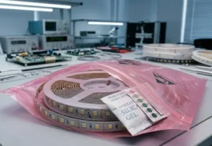
Our technical support team fields calls from contractors and wholesalers who just finished an LED strip installation — only to see annoying flicker the moment they power it on incompatible dimmers 1. It is frustrating. You followed the spec sheet, used decent products, and the result still looks unprofessional. The good news? In most cases, the strip itself is perfectly fine.
LED strip flickering after installation is usually caused by an underpowered or failing power supply, loose wiring connections, incompatible dimmers, or voltage drop on long runs. Systematically checking each of these — starting with the easiest fix — will resolve the issue without replacing the entire strip.
Below, we walk through the most common post-installation flicker scenarios. Each section targets a specific symptom so you can match what you see to the most likely cause — and fix it fast.
How do I troubleshoot if my power supply is causing my LED strips to flicker?
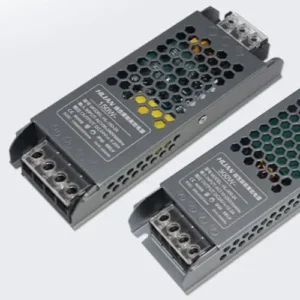
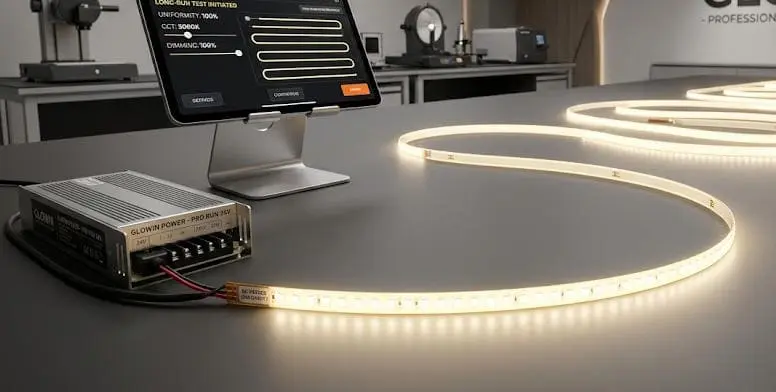
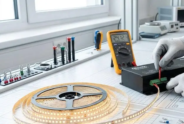
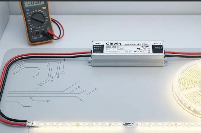
When we test finished reels before shipment, we use lab-grade power supplies 2 to guarantee the strip performs as rated. But once the product reaches a job site, the power supply chosen by the installer becomes the weakest link. A flickering strip that worked perfectly on our test bench almost always points back to the PSU. underpowered or failing power supply 3
To troubleshoot a power supply causing LED strip flicker, check that its output voltage matches the strip rating, confirm its wattage exceeds the strip's total load by at least 20%, and swap in a known-good PSU to see if the flicker disappears. A failing or undersized driver is the most common cause.
Check the Voltage Rating First
LED strips are designed for a specific DC voltage — usually 12V or 24V. If your power supply outputs the wrong voltage, the strip will not run properly. Even a small mismatch can produce visible flicker or dim sections. Always read the label on both the strip and the driver before connecting anything.
Confirm Your Wattage Budget
This is where many installers run into trouble. A 60W power supply driving 55W of LED strip might seem fine on paper. But in practice, running a PSU near its maximum load generates heat, causes output instability, and shortens the driver's life. We recommend a 20% buffer at minimum.
Here is a quick reference:
| Total Strip Wattage | Minimum PSU Rating (with 20% buffer) | Recommended PSU Rating |
|---|---|---|
| 30W | 36W | 40W–50W |
| 60W | 72W | 80W–100W |
| 100W | 120W | 130W–150W |
| 150W | 180W | 200W |
Swap-Test With a Known-Good PSU
The fastest way to confirm a power supply problem is to temporarily connect the strip to a different, known-good PSU. If the flicker stops, the original driver is the issue. This single test can save hours of chasing phantom wiring problems. In one real-world case we supported, a contractor in Melbourne replaced a failing 24V driver and the entire 15-meter installation returned to perfect operation — no need to touch the strip at all.
Look for Signs of PSU Degradation
Power supplies do not last forever. Capacitors age 4, especially in hot or poorly ventilated enclosures. Watch for these warning signs:
- Audible buzzing or whining from the driver
- The output voltage drifts when measured with a multimeter
- The flicker gets worse as the driver warms up
- The driver shuts off intermittently under load
If you see any of these, replace the PSU. Do not try to repair it. A quality Mean Well 5 or equivalent driver is inexpensive compared to the labor cost of a second site visit.
Why This Matters for Project Installations
For our wholesale and contractor clients, we always stress PSU quality in our spec documents. A cheap power supply can undermine the best LED strip on the market. When you are bidding a project or specifying materials, include the driver as a line item — not an afterthought.
Why are my project-grade LED strips flickering when I use my current dimmer?
Our engineering team spends a lot of time helping clients match dimmers to our strips. It is one of the most overlooked compatibility issues in LED installations. You buy a high-quality strip, pair it with a dimmer you had on hand, and the result is a maddening flicker — especially at low brightness levels.
Project-grade LED strips flicker with incompatible dimmers because many dimmers use a modulation method or frequency that does not match the strip's driver. To fix this, use a PWM dimmer rated for LED use, ensure its frequency is above 1,000 Hz, and confirm it is compatible with your specific driver model.
The Root Cause: Dimmer–Driver Mismatch
Traditional incandescent dimmers use leading-edge or trailing-edge phase-cut technology. These dimmers chop the AC waveform to reduce power. LED drivers do not always respond well to this. The result is flicker, buzzing, or a strip that refuses to dim below a certain level.
For constant-voltage LED strips, a dedicated 0–10V, DALI, or PWM dimmer paired with a dimmable driver is the correct approach. Do not try to use a $5 wall dimmer designed for halogen bulbs.
PWM Frequency Matters
PWM (Pulse Width Modulation 6) dimmers work by rapidly switching the LED on and off. If the switching frequency is too low, you see flicker. Visible flicker generally occurs below 100 Hz. For comfortable, flicker-free dimming, aim for a PWM frequency above 1,000 Hz. Some high-end controllers operate at 20,000 Hz or higher, which eliminates flicker even on camera.
| Dimmer Type | Typical Frequency | Flicker Risk | Best Use |
|---|---|---|---|
| Phase-cut (leading edge) 7 | 50–60 Hz (mains) | High | Incandescent / halogen only |
| Phase-cut (trailing edge) | 50–60 Hz (mains) | Medium–High | Some dimmable LED drivers |
| PWM (low frequency) | 100–500 Hz | Medium | Basic LED dimming |
| PWM (high frequency) | 1,000–25,000 Hz | Very Low | Project-grade LED strips |
| 0–10V / DALI | Analog signal | Very Low | Commercial installations |
How to Isolate a Dimmer Problem
Here is a simple test. Bypass the dimmer entirely by connecting the strip directly to the driver at full power. If the flicker disappears, the dimmer is the problem. This takes less than five minutes and saves you from replacing components that are actually fine.
Wireless Controllers and Flickering
We have seen cases where wireless controllers — especially budget RF or Wi-Fi modules — introduce flicker during pairing, signal drops, or firmware glitches. If you use a wireless system, test the strip with a wired controller first to rule this out.
Our Recommendation for Contractors
When we ship project-grade strips to clients in Germany and Australia, we include a compatibility note listing tested dimmer and driver combinations. If you are unsure, ask your strip supplier for a tested pairing list. This one step prevents the most common dimmer-related callbacks.
How can I fix flickering issues caused by voltage drop in my long-run installation?
Long-run installations are one of our specialties. We manufacture strips designed for continuous runs up to 20 meters and beyond. But even the best strip will flicker or dim at the far end if the installation does not account for voltage drop 8. This is a physics problem, not a product defect.
To fix voltage-drop flickering in long LED strip runs, inject power at both ends or at regular intervals along the strip, use thicker gauge wires (14 AWG or lower for runs over 5 meters), and keep wire lengths as short as possible. This ensures consistent voltage across the entire installation.

What Is Voltage Drop and Why Does It Cause Flicker?
Every wire has resistance. The longer the wire and the thinner its gauge, the more voltage it loses between the power supply and the strip. A 24V strip that only receives 21V at its far end will show dimming, color shift, and flicker. The LEDs at the end are essentially starved of power.
How to Calculate Voltage Drop
You do not need complex math. A simple rule of thumb: keep the total voltage drop below 5% of your supply voltage. For a 24V system, that means no more than 1.2V of drop across your wiring and strip combined.
| Wire Gauge (AWG) | Max Recommended Run (at 3A load) | Voltage Drop per 10m |
|---|---|---|
| 22 AWG | 2m | ~1.1V |
| 18 AWG | 5m | ~0.4V |
| 16 AWG | 8m | ~0.25V |
| 14 AWG | 12m | ~0.16V |
| 12 AWG | 18m+ | ~0.10V |
These values are approximate and depend on the specific current draw of your strip. Always measure with a multimeter at the far end of the installation to confirm.
Power Injection: The Best Solution
Power injection means feeding power to the strip at multiple points instead of just one end. For a 10-meter run, you might inject power at the start and at the 5-meter mark. For a 20-meter run, inject at the start, middle, and end. This dramatically reduces the distance that current must travel through the strip's thin copper traces.
Shorter, Thicker Wires Win Every Time
We have seen contractors use long, thin extension wires to reach a power supply mounted far from the strip. This adds resistance and makes voltage drop worse. One of our clients in a hospitality project replaced 3 meters of 22 AWG leads with 1 meter of 14 AWG wire. The flicker at the far end of the strip disappeared completely.
When to Use 24V Instead of 12V
Higher voltage strips lose proportionally less voltage over distance. A 24V strip experiencing a 1V drop still operates at 95.8% of rated voltage. A 12V strip with the same 1V drop operates at only 91.7%. For any run longer than 5 meters, we strongly recommend 24V strips. This is standard advice we give to every project customer.
Practical Tips for Installers
- Always measure voltage at the far end of the strip with a multimeter before finalizing the install.
- Plan wire routing to minimize length. Keep the PSU as close to the strip as possible.
- Use bus wiring (parallel power feeds) for very long architectural runs.
- If you see the far end of the strip looking slightly dimmer or warmer in color, voltage drop is already present — even if flicker has not started yet.
What should I check in my connections if my newly installed LED strips are flashing?
On our production floor, every solder joint is inspected under magnification before a reel ships. But once the strip reaches the field, new connections are made — and that is where problems start. Loose connectors, cold solder joints 9, and reversed polarity are responsible for a huge share of post-installation flicker.
If your newly installed LED strips are flashing, check all physical connections first: tighten screw terminals, reseat or replace snap connectors, inspect solder joints for cracks, verify correct DC polarity, and confirm your wire gauge is adequate. Intermittent flashing almost always traces back to a poor or unstable connection point.

Snap Connectors vs. Soldered Joints
Snap-on (clip) connectors are fast and convenient. But they are also the most common failure point we see in field installations. The metal contacts inside these connectors can lose grip over time, especially in warm environments or where vibration is present. A joint that seems solid during installation can loosen weeks later.
Soldered connections, when done correctly, are far more reliable. If you are installing strips in a permanent or commercial setting, we always recommend soldering over snap connectors.
How to Inspect a Connection
- Visual check: Look for blackened, cracked, or dull solder joints. A good solder joint is shiny and smooth.
- Tug test: Gently pull each wire. It should not move. If it does, the joint is weak.
- Wiggle test: While the strip is powered on, gently wiggle each connection point. If the strip flickers when you touch a joint, you have found the problem.
- Multimeter continuity: Use a multimeter set to continuity mode. Touch the probes to both sides of the connection. A solid joint shows near-zero resistance.
Polarity Errors
LED strips require correct DC polarity 10. Reversing positive and negative will not always blow the strip — but it can cause erratic behavior, including flashing or no output. Always double-check the polarity markings on the strip and the wire colors from the PSU. Red is typically positive. Black is negative. But do not assume — verify with a multimeter.
Wire Gauge and Connection Quality
Thin wires create high resistance at the connection point. This resistance generates heat and can cause intermittent contact. For any installation drawing more than 2A, use at least 18 AWG wire. For higher-current runs, go to 16 or 14 AWG.
Terminal Blocks and Screw Connections
If you are using terminal blocks or screw-type connectors, make sure the screws are fully tightened. A partially tightened screw allows the wire to shift, creating intermittent contact. We have seen entire installations fixed simply by re-torquing a single loose screw terminal.
Strip-to-Strip Joints
When you cut and rejoin strips, the quality of that joint matters. A poorly aligned solder pad or a connector that does not make full contact with the copper pad can cause one section to flash while the rest works fine. If only one section flickers, start by inspecting the joints on either side of that section.
A Quick Diagnostic Approach
- Power off the installation.
- Inspect every connection from PSU to strip, including intermediate joints.
- Reseat or resolder any suspect connection.
- Power on and observe.
- If flicker persists, disconnect sections one at a time to isolate the faulty joint or segment.
This methodical approach takes 10 to 15 minutes and resolves the majority of connection-related flicker problems.
Conclusion
Most LED strip flicker after installation comes down to the power supply, the connections, the dimmer, or voltage drop — not the strip itself. Work through each cause systematically, starting with the simplest check, and you will solve the problem quickly.
Footnotes
- Details why traditional dimmers are incompatible with LEDs and solutions. ↩︎
- Describes the characteristics and importance of laboratory power supplies. ↩︎
- Explains common LED driver failure modes and troubleshooting steps. ↩︎
- Explains the degradation mechanisms and lifespan of electrolytic capacitors. ↩︎
- Official website of a leading manufacturer of switching power supplies. ↩︎
- Defines and explains the principle of Pulse Width Modulation in electronics. ↩︎
- Describes phase-cut dimming methods, including leading-edge technology. ↩︎
- Provides a fundamental explanation of voltage drop in electrical circuits. ↩︎
- Explains what cold solder joints are and how to prevent them in electronics. ↩︎
- Explains the concept of direct current polarity in electrical applications. ↩︎