Every week on our production line, we see the same request: brighter, brighter, brighter PCB substrates 1. But after years of engineering custom LED strips for contractors worldwide, we've learned that chasing raw lumens without a thermal plan is a recipe for premature failure and unhappy clients.
Balancing brightness and heat dissipation requires selecting appropriate PCB substrates, specifying adequate thermal accessories like aluminum profiles, using real-time temperature monitoring, and sometimes choosing two lower-power strips instead of one high-power strip to distribute heat and extend operational lifespan.
High brightness is essentially trading lifespan for luminous output—no exceptions aluminum profiles 2. We usually advise clients not to blindly chase high wattage. Instead, check whether the installation environment has sufficient cooling—aluminum channels, airflow, ambient temperature LED junction temperatures 3. If cooling is limited, layering two low-power strips often outperforms one high-power strip pushed to its thermal limit. Once temperature climbs, lumen depreciation accelerates. Many project failures aren't caused by insufficient brightness at the start. They're caused by brightness dropping too fast. That balance point must be decided before a single meter of strip is installed. Let's break down exactly how to get it right.
How do I choose the right PCB thickness to manage heat in my high-lumen LED strip projects?
We prototype dozens of high-lumen strip designs each quarter, and PCB thickness is one of the first decisions our engineers debate. Get it wrong, and no amount of external heatsinking will save the project.
For high-lumen LED strips, choose a minimum 2oz copper PCB thickness. For strips exceeding 20W/m, upgrade to 3oz or even 4oz copper. Thicker copper layers spread heat laterally faster, lowering LED junction temperatures and protecting both brightness and lifespan over thousands of hours.
Why PCB Thickness Matters More Than You Think
The PCB is the first thermal pathway. Heat generated at the LED junction must travel through the solder pad, into the copper trace, and then into the PCB substrate before it ever reaches an external heatsink. If the copper layer is too thin, it creates a thermal bottleneck. The heat stays trapped near the LED chip. Junction temperature rises. Efficiency drops. Color shifts. Life shortens.
Think of it like a highway. A two-lane road can handle moderate traffic. But during rush hour, you need four lanes. High-lumen strips are always in rush hour. More wattage means more thermal traffic, and the copper layer is your road width.
Standard vs. Heavy Copper: A Practical Comparison
| PCB Copper Weight | Typical Use Case | Thermal Conductivity 4 Performance | Recommended Max Power Density |
|---|---|---|---|
| 1oz (35µm) | Decorative, ≤10W/m | Baseline | 10W/m |
| 2oz (70µm) | General commercial, 10–20W/m | ~40% better lateral spreading vs. 1oz | 20W/m |
| 3oz (105µm) | High-output architectural, 20–30W/m | ~70% better lateral spreading vs. 1oz | 30W/m |
| 4oz (140µm) | Extreme luminosity, 30W/m+ | ~100% better lateral spreading vs. 1oz | 40W/m+ |
When we fulfill orders for projects in Australia where ambient temperatures can exceed 40°C, we default to 2oz minimum. For long-run installations in enclosed coves—where airflow is near zero—we push clients toward 3oz. The cost increase is modest. The reliability improvement is significant.
Don't Forget Substrate Material
Copper weight is only part of the equation. The base substrate matters too. Standard FR4 has poor thermal conductivity—around 0.3 W/mK. Aluminum-core PCBs (MCPCBs) 5 jump to 1.0–2.0 W/mK. For extreme applications, ceramic substrates can reach 20+ W/mK, though cost and flexibility suffer.
For most high-brightness LED strip projects, an aluminum-core PCB with 2oz or 3oz copper is the sweet spot. It balances cost, manufacturability, and thermal performance. We've tested this combination extensively on our lines and the results are consistent: junction temperatures drop 10–15°C compared to FR4 at the same power density.
A Word on Flexibility
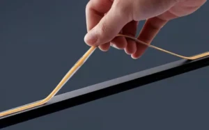
Thicker copper means stiffer PCB. If your project requires tight bending radii—curved coves, radius under 50mm—a 3oz or 4oz board won't flex well. In these cases, consider using a 2oz flexible PCB and compensating with better external thermal management. It's always a system-level decision.
What thermal management accessories should I specify for my extreme luminosity installations?
When we ship high-brightness strips to electrical contractors in Germany, the conversation never stops at the strip itself. The accessories you specify around the strip determine whether the system thrives or fails within months.
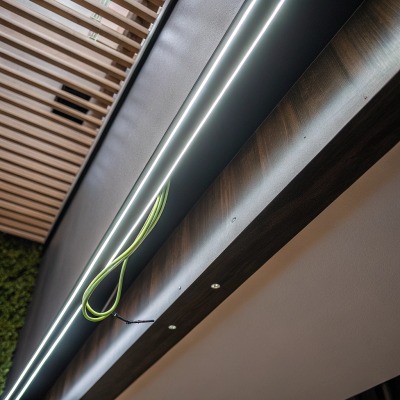
For extreme luminosity installations, specify aluminum extrusion profiles with adequate cross-sectional area, thermal adhesive tape or paste for strip-to-profile bonding, and ensure surrounding airflow or ventilation. In confined spaces, consider active cooling or oversized profiles to compensate for restricted convective dissipation.
The Aluminum Profile Is Non-Negotiable
An aluminum extrusion profile serves as the primary heatsink for most LED strip installations. It absorbs heat from the PCB rear surface and radiates it into the surrounding air. Without one, even a well-designed 2oz copper strip will overheat at power densities above 14W/m in a typical indoor environment.
But not all profiles are equal. A slim decorative profile with a 10mm × 6mm cross-section cannot dissipate the same heat as a recessed profile measuring 30mm × 20mm. Surface area is everything. More aluminum mass and more exposed surface area mean more heat can leave the system.
Matching Profile to Power Density
| Strip Power Density | Minimum Recommended Profile Size | Installation Condition | Notes |
|---|---|---|---|
| ≤10W/m | Small surface-mount (15mm × 6mm) | Open air, good ventilation | Decorative applications |
| 10–20W/m | Medium recessed (20mm × 12mm) | Semi-enclosed cove | Standard commercial projects |
| 20–30W/m | Large recessed or suspended (30mm × 20mm) | Enclosed or warm ambient | Ensure thermal tape contact |
| 30W/m+ | Oversized or custom profile (40mm+ width) | High ambient, no airflow | Consider active cooling assist |
Thermal Interface Materials
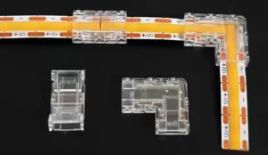
The bond between the LED strip and the aluminum profile is critical. An air gap—even a tiny one—acts as an insulator. We recommend thermal adhesive tape 6 rated at 1.0 W/mK or higher. For extreme cases, thermal paste applied before mechanical clamping provides even better contact. The goal is zero air between the strip's back surface and the profile's inner channel.
When Passive Cooling Isn't Enough
In some projects, passive heatsinking simply cannot keep up. Enclosed ceiling slots with no airflow. Outdoor installations in tropical climates. Industrial environments near heat-generating equipment. In these scenarios, you have several options:
- Ventilation fans: Small, low-noise fans at profile ends create forced airflow through the channel.
- Larger profiles: Doubling the profile cross-section can drop temperatures by 8–12°C.
- Two strips instead of one: This is our most frequent recommendation. Instead of one 30W/m strip, use two 15W/m strips on parallel profiles. You get the same total output with dramatically better heat distribution. Each strip runs cooler, lasts longer, and maintains color consistency.
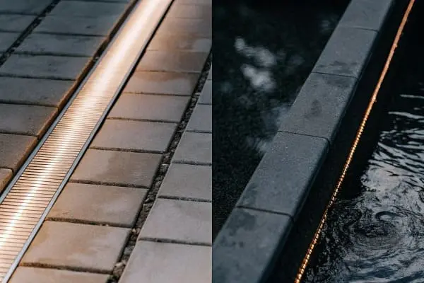
Weatherproofing and Sealing Considerations
For outdoor or wet-area installations, IP67 or IP68 silicone extrusions add another thermal layer. Silicone is a moderate insulator, so it traps some heat. Factor this into your thermal budget. If you're using a silicone-sleeved strip at 20W/m, treat it thermally as if it's 25W/m and size your profile accordingly.
How can I prevent heat-induced color shifting in my high-power LED lighting designs?
Color consistency is one of the strictest requirements our clients in architectural lighting demand. When we run QC on our production batches, we test for color deviation under thermal stress—because what looks perfect at 25°C can drift noticeably at 70°C.
To prevent heat-induced color shifting, maintain LED junction temperatures below the manufacturer's rated maximum, use LED chips with tight binning tolerances, design thermal systems that keep operating temperatures stable, and select drivers with constant-current regulation to prevent overdrive-related thermal spikes.
How Heat Causes Color Shift
LED phosphor chemistry is temperature-sensitive. As junction temperature rises, the phosphor conversion efficiency changes. In most white LEDs, higher temperatures cause a shift toward the blue end of the spectrum. The warm white you specified at 3000K may drift to 3200K or higher under sustained heat. In critical applications—hotel lobbies, retail displays, museum lighting—this drift is visible and unacceptable.
Additionally, different LED chips within the same strip may heat unevenly. LEDs near the power feed run cooler. LEDs at the far end of a long run may heat more. This creates a visible color gradient along the strip's length.
Binning and Consistency at the Source
Color consistency starts at the chip level. LED manufacturers sort chips into "bins" based on color coordinates, forward voltage, and luminous flux. Tight binning means all chips in a batch fall within a narrow range—typically within a 3-step MacAdam ellipse 8 for premium applications.
When we source LEDs for architectural projects, we specify 3-step SDCM maximum. We also request single-bin lots for large projects. This means every reel ships with chips from the same production bin. The visual uniformity across hundreds of meters is dramatically better than mixed-bin sourcing.
Thermal Design Strategies for Color Stability
| Strategy | Effect on Color Stability | Implementation Difficulty |
|---|---|---|
| Adequate aluminum heatsinking | Keeps junction temp stable; prevents drift | Low |
| Constant-current LED driver | Prevents current spikes that cause local heating | Low |
| Single-bin LED sourcing | Eliminates inter-chip color variation | Medium (supply chain) |
| Derating strip power (run at 80% max) | Reduces thermal load; improves consistency | Low |
| Thermal paste interface | Eliminates hot spots from air gaps | Low |
| Active temperature monitoring | Alerts before drift occurs | Medium |
Derating: The Most Underused Trick
Running a strip at 80% of its rated maximum power is one of the simplest ways to improve color stability. At reduced power, junction temperatures stay lower, phosphor stress decreases, and the strip operates well within its safe thermal envelope. The brightness reduction is often imperceptible, especially when the strip was over-specified to begin with.
On our production line, we test every strip at full rated power and at 80% power. The color difference at 80% load after 1,000 hours of accelerated aging is consistently less than 1 SDCM step. At 100% load in a poorly ventilated setup, that same strip can drift 2–3 steps. The lesson is clear: a small power reduction buys significant color stability.
Driver Quality Matters
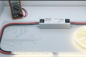
A cheap driver with poor current regulation will cause flickering and micro-surges that create uneven heating. Over time, this accelerates phosphor degradation and causes inconsistent color. Always specify drivers with ≤3% current ripple and proper thermal protection. When we bundle drivers with our strip orders, we test the combination as a system, not just as separate components.
How do I verify that my custom high-brightness strips won't overheat during long-run operation?
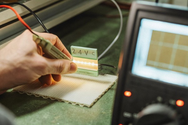
Before we ship a single reel to a client, our QC team runs thermal validation on every new custom design. We've learned the hard way—from early project callbacks—that lab performance and real-world performance can diverge dramatically if you don't test under realistic conditions.
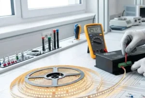
To verify high-brightness strips won't overheat during long runs, conduct thermal testing with strips mounted on the actual heatsink profile, run them at full power for a minimum of 4 hours, and measure surface temperatures at multiple points. Junction temperature should stay below 85°C in typical applications to ensure rated lifespan.
Step 1: Define Your Thermal Budget
Before testing, establish your temperature ceiling. Most mid-to-high-end LED chips are rated for junction temperatures up to 120°C, but operating near that limit destroys lifespan. A practical target is 80–85°C junction temperature for a 50,000-hour L70 lifespan. Every 10°C above that roughly halves usable life.
Your thermal budget calculation starts with ambient temperature. If the installation is in an Australian summer where ambient hits 45°C, you have only 35–40°C of headroom before reaching your junction limit. That's far less margin than a climate-controlled German office at 22°C ambient.
Step 2: Test Under Realistic Conditions
Testing a strip loose on a bench means nothing. Mount the strip inside the actual aluminum profile you plan to use. Attach the diffuser. If the project is recessed into a ceiling, build a mock cavity. Seal it the way it will be sealed on-site. Then power the strip at full rated wattage and let it run.
We use K-type thermocouples attached directly to the strip surface at three points: near the feed end, at the midpoint, and at the far end. We also place a thermocouple on the exterior of the aluminum profile. Data loggers record temperature every 30 seconds for at least 4 hours—long enough for the system to reach thermal equilibrium.
Step 3: Interpret Your Results
| Measurement Point | Acceptable Range | Warning Zone | Critical / Redesign |
|---|---|---|---|
| Strip surface near feed | ≤55°C | 55–65°C | >65°C |
| Strip surface at far end | ≤60°C | 60–70°C | >70°C |
| Profile exterior surface | ≤45°C | 45–55°C | >55°C |
| Estimated junction temp* | ≤85°C | 85–100°C | >100°C |
*Junction temperature is estimated by adding 10–20°C to the measured strip surface temperature, depending on the LED package.
If any measurement lands in the warning zone, consider derating, upgrading the profile, or improving airflow. If anything hits the critical zone, the design needs revision before deployment.
Step 4: Long-Duration Burn-In
For mission-critical projects—hospitals, transit stations, high-profile retail—we recommend a 72-hour continuous burn-in test. This catches intermittent driver issues, thermal paste failures, and solder joint weaknesses that a 4-hour test might miss. We run these extended tests on every custom order above 500 meters.
Step 5: Document and Share
After testing, compile a thermal test report. Include photos of the test setup, temperature curves, ambient conditions, and pass/fail conclusions. We provide these reports to our clients as part of the project documentation package. It gives contractors and specifiers confidence during installation sign-off and protects everyone if questions arise later.
Smart Monitoring for Ongoing Assurance
For installations that are difficult to inspect after commissioning—recessed coves, exterior facades, signage channels—embedding a simple NTC thermistor at a critical point allows ongoing remote temperature monitoring. When connected to a smart controller, the system can dim the strip automatically if temperatures exceed a set threshold. This protects the investment for years without manual intervention.
Conclusion
Brightness without thermal planning leads to fast lumen depreciation and project failure. Choose the right PCB, specify proper accessories, protect color consistency, and validate with real testing. That's how lasting high-brightness LED installations are built.
Footnotes
- Explains the role and types of PCB substrate materials in electronics. ↩︎
- Details how aluminum profiles act as heat sinks for LED strips and their benefits. ↩︎
- Defines LED junction temperature and its critical impact on performance and lifespan. ↩︎
- Provides a comprehensive definition and explanation of thermal conductivity in materials. ↩︎
- Explains the advantages and applications of aluminum-core PCBs for effective thermal management. ↩︎
- Describes how thermal adhesive tapes provide a heat-transfer path in electronic assemblies. ↩︎
- Discusses the crucial role of phosphor chemistry in LED efficiency, light quality, and stability. ↩︎
- Defines the 3-step MacAdam ellipse in relation to LED color consistency and binning standards. ↩︎
- Explains L70 lifespan as an industry standard for LED light output depreciation over time. ↩︎
- Defines NTC thermistors as temperature-sensitive resistors used for precise temperature monitoring. ↩︎