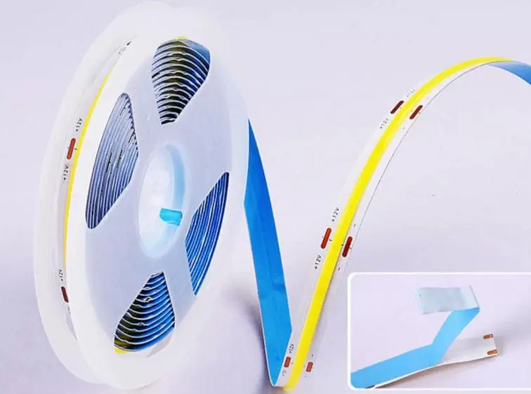
Every time our production line runs a new batch of COB LED strips 1, the first thing we check isn't brightness at full power — it's what happens when voltage drops below spec. Flickering, dark spots, uneven glow — these are the silent killers of premium lighting projects, and they only show up when conditions aren't ideal. If you've ever installed a beautiful strip only to get complaints about dim patches near the end of a long run, you know the frustration.
To test low-voltage startup performance of high-density dotless COB LED strips, gradually reduce input voltage below the rated level using an adjustable DC power supply while monitoring illumination uniformity, inrush current, and voltage drop along the strip with a multimeter or oscilloscope. This reveals design margin and real-world reliability.
Low-voltage startup testing is one of the most practical quality checks you can perform — whether you're a distributor evaluating a new supplier or a contractor preparing for a critical project. Let me walk you through the exact methods, tools, and benchmarks our team uses every day.
How can I accurately measure the minimum startup voltage for my high-density COB LED strips?
When we calibrate test stations for outgoing quality control, we always start with minimum startup voltage. It's the single number that tells us the most about a strip's internal design and component quality.
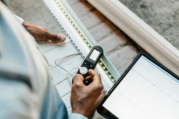
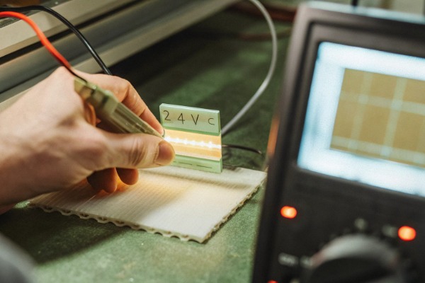
To accurately measure minimum startup voltage, connect the COB strip to a variable DC power supply, slowly increase voltage from zero, and record the exact point where the entire strip illuminates uniformly without flickering or dark segments. Use a digital multimeter at the input and far end simultaneously.
Why Minimum Startup Voltage Matters
The minimum startup voltage is the lowest voltage at which every LED chip on the strip turns on and produces visible, even light. For high-density COB strips, this is critical because hundreds of tiny chips sit closely together on the flexible PCB. If even a small group fails to light at low voltage, the "dotless" effect breaks down immediately.
In real installations, voltage at the strip is almost never exactly what the power supply label says. Wire runs, connector resistance, and shared circuits all pull voltage down. Our engineers have found that a well-designed 24V COB strip should reliably start at 20V or even lower. Strips that need 23V or more to look uniform have very little design margin.
Step-by-Step Measurement Procedure
- Cut a sample length — typically 0.5 meters or 1 meter.
- Connect it to an adjustable DC power supply 2. Set current limit to 1.5x the strip's rated current per meter.
- Start at 0V. Slowly increase voltage in 0.5V increments.
- At each step, observe the strip visually. Note the voltage where the first light appears.
- Continue increasing until the strip is fully and evenly lit. Record this as the minimum startup voltage.
- Place a multimeter at the far end of the strip to check for voltage drop even on this short sample.
What the Numbers Tell You
| Parameter | Good Result | Marginal Result | Poor Result |
|---|---|---|---|
| First light appears (24V strip) | Below 16V | 16V–19V | Above 19V |
| Full uniform illumination | Below 20V | 20V–22V | Above 22V |
| Voltage drop on 1m sample at rated current | Less than 0.3V | 0.3V–0.6V | Above 0.6V |
| Flickering during ramp-up | None | Occasional | Persistent |
If a strip only lights uniformly above 22V on a 24V system, you have almost no margin for real-world voltage sag. That means long wire runs or slightly undersized power supplies will cause visible problems on site.
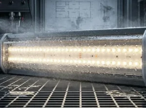
Cold-Start Testing
Temperature affects LED forward voltage 3. In our testing room, we also check startup at 5°C and 35°C. Cold environments raise the forward voltage slightly, meaning the strip needs a bit more voltage to start. If your projects include outdoor or unheated spaces, cold-start data is essential. A 10°C drop can shift the forward voltage by 20–30mV per chip. On a strip with many chips in series, that adds up.
Why is consistent low-voltage performance essential for the visual uniformity of my dotless lighting projects?
Our R&D team spent months perfecting the phosphor layer on our COB strips, but even the best phosphor can't hide electrical inconsistency. If the voltage dips unevenly, the "dotless" promise falls apart.
Consistent low-voltage performance ensures every section of the COB strip receives enough energy to produce equal brightness and color temperature, preserving the seamless, dot-free appearance that defines premium architectural lighting. Without it, visible banding and color shifts ruin the project.
The Physics Behind Uneven Light
High-density COB strips pack LEDs so close together that the human eye perceives a continuous line of light. But each chip is still an individual semiconductor. Each one has a slightly different forward voltage. When the system voltage is comfortably above all individual forward voltages, differences are invisible. When voltage drops close to the threshold, some chips dim before others. This creates visible banding — bright and dark zones that defeat the whole point of COB technology.
How Voltage Drop Creates Visual Problems
In a 5-meter installation powered from one end, current flows through the copper traces on the PCB. Resistance in these traces causes a progressive voltage drop. The chips at the far end receive less voltage. Under normal conditions, the difference might be barely noticeable. But in a low-voltage scenario — say the power supply sags during a building-wide load spike — the far-end chips may fall below their turn-on threshold entirely.
This is why we test every production batch with a slow voltage ramp. We want to see how the strip behaves not just at rated voltage, but in the 15%–20% below rated voltage range. That's where the truth comes out.
Color Temperature Shift Under Low Voltage
It's not only brightness that changes. When LEDs are driven below their optimal current, the spectral output shifts. Warm white strips may appear slightly more amber. Cool white strips may look greenish. For architectural and hospitality projects where color consistency is a selling point, this is unacceptable. Our quality control team measures CCT (correlated color temperature 4) at rated voltage and at 85% of rated voltage. The difference should be less than 100K.
Real-World Impact on Project Quality
| Scenario | Voltage at Strip End | Visual Result |
|---|---|---|
| Short run, adequate supply | 23.5V–24V | Perfect uniformity |
| Medium run, adequate supply | 22V–23V | Slight dimming at far end, usually acceptable |
| Long run, marginal supply | 20V–21V | Noticeable brightness gradient |
| Long run, undersized supply | Below 20V | Dark patches, color shift, possible flickering |
I recall a project where a contractor in Germany called us about a cove lighting job. The strips looked great on his bench but showed visible banding after a 7-meter run in the ceiling. The issue was not the strip itself — it was the 0.75mm² wire feeding it. After switching to 1.5mm² wire and adding mid-point power injection, the problem disappeared. Low-voltage startup testing would have predicted this.
What tools and equipment do I need to conduct a professional startup test on my LED strips?
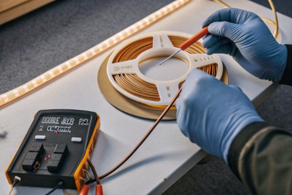
When we set up our QC station, we chose tools that balance accuracy, speed, and cost. You don't need a university lab, but you do need more than a basic multimeter.
A professional startup test requires an adjustable DC power supply with current limiting, a digital multimeter for voltage and current readings, an optional oscilloscope for transient analysis, a temperature-controlled environment or thermometer, and a camera for visual documentation. These tools let you measure startup voltage, inrush current, and uniformity accurately.
The Essential Tool Kit
Here is what we recommend for anyone serious about evaluating COB strip quality — whether you're a distributor running incoming inspections or a contractor checking product before a big install.
| Tool | Purpose | Approximate Cost | Essential or Optional |
|---|---|---|---|
| Adjustable DC power supply (0–30V, 10A+) | Control voltage precisely, set current limits | $80–$250 | Essential |
| Digital multimeter 5 (True RMS) | Measure voltage and current at multiple points | $30–$100 | Essential |
| Oscilloscope 6 (at least 20 MHz) | Capture inrush current 7 and voltage transients | $200–$500 | Recommended |
| Infrared thermometer or thermal camera | Monitor temperature during startup and steady state | $30–$300 | Recommended |
| Ambient thermometer | Record room temperature during tests | $10 | Essential |
| Wire in multiple gauges (18 AWG, 16 AWG) | Simulate different installation wire resistance | $10–$20 | Optional |
| Notebook or logging software | Record all data for comparison across batches | Free–$50 | Essential |
How to Use Each Tool
Adjustable DC power supply: This is your most important piece of equipment. Set the voltage to zero. Connect the strip. Slowly increase voltage while watching the strip and the multimeter. The current-limiting feature protects both the strip and the supply during inrush testing. Set the current limit about 50% above the strip's rated current per meter for the length you're testing.
Digital multimeter: You need at least two readings — voltage at the input pads and voltage at the far end of the strip. If you only have one multimeter, take the far-end reading first (it's the one most likely to show problems), then switch to the input side. For current measurement, connect the multimeter in series between the power supply positive terminal and the strip's positive pad. Never connect it in parallel when measuring current.
Oscilloscope: This is where you see things a multimeter can't show. During the first 100–200 milliseconds after power-on, inrush current can spike to 1.5x or even 2x the steady-state value. The oscilloscope captures this spike. It also reveals any voltage ringing or oscillation that might cause flickering invisible to the naked eye but captured by cameras. For projects involving video or film environments, this test is critical.
Setting Up Your Test Bench
Keep the ambient temperature consistent — ideally 22°C–25°C. Tape the strip flat on a non-conductive surface. Use short, thick wires between the power supply and the strip to minimize external voltage drop. Label each test with the date, batch number, strip model, and ambient temperature. Over time, these records become invaluable for comparing suppliers or catching quality drift.
A Note on Safety
Always start with the voltage at zero and increase slowly. High-density COB strips can draw significant current. A 5-meter strip at 14W/m draws about 3 amps at 24V. If you accidentally short the pads, the power supply's current limiter should protect everything — but only if you've set it correctly. Double-check polarity before every test. Reverse polarity can damage the strip permanently.
How does low-voltage startup stability impact the long-term reliability of my custom OEM lighting solutions?
In our experience exporting custom-branded strips to Australia and Germany, the first question from serious buyers is never about price — it's about what happens after 10,000 hours and 5,000 power cycles. Low-voltage startup behavior is a powerful predictor of long-term reliability.
Low-voltage startup stability directly impacts long-term reliability because repeated exposure to undervoltage conditions stresses LED junctions, degrades solder joints, and accelerates driver component fatigue. Strips that perform well under low-voltage startup tests consistently show lower field failure rates over years of operation.
Why Startup Is the Hardest Moment for a LED Strip
Every power-on event is a thermal and electrical shock. The strip goes from ambient temperature to operating temperature in seconds. Current rushes in before the system stabilizes. Components expand. Solder joints flex microscopically. For high-density COB strips, this stress is concentrated because so many chips share a small PCB area.
Strips with tight design margins — those that barely start at rated voltage — experience much greater stress during each power cycle. The chips that are slowest to turn on may briefly carry more current as the driver tries to regulate output. This localized overcurrent accelerates junction degradation.
The Connection Between Startup Margin and Lifespan
Think of it this way: a strip with a minimum startup voltage of 18V on a 24V system has 6V of margin. A strip that needs 23V has only 1V. In a real building, voltage fluctuations of 1–2V are common, especially during peak hours. The second strip will experience partial shutdown events — some chips turning off and back on — dozens of times per day. Each event is a mini power cycle that wears the components.
Our durability tests simulate this by running strips through 10,000 power cycles at 85% of rated voltage. We then compare them to strips cycled at 100% rated voltage. The low-margin strips consistently show faster lumen depreciation 9 and more solder joint failures.
Impact on OEM Brand Reputation
If you're building a private-label lighting brand — as many of our Australian and German partners do — reliability is your reputation. A contractor who installs your product in 50 hotel rooms doesn't want callbacks in year two. Low-voltage startup testing during incoming quality inspection is one of the fastest ways to screen for potential reliability issues before the product reaches the field.
Key Reliability Metrics to Track
Here are the metrics we track and share with our OEM partners:
| Metric | Test Method | Target for Premium Products |
|---|---|---|
| Minimum startup voltage | Voltage ramp test | Below 83% of rated voltage |
| Inrush current ratio | Oscilloscope at power-on | Less than 1.5x steady-state current |
| Startup uniformity | Visual inspection at 85% voltage | No visible dark spots or flicker |
| Lumen maintenance after 5,000 cycles at 85% voltage | Integrating sphere measurement | Above 95% of initial output |
| Solder joint integrity10 after 5,000 cycles | Microscope inspection | No cracks or delamination |
Practical Advice for Procurement Teams
When evaluating a new COB strip supplier, request startup test data. If they can't provide it, run the test yourself on samples before committing to a large order. A 30-minute bench test with an adjustable power supply can save you from thousands of dollars in warranty claims. We provide this data proactively to every OEM partner because we know it builds trust and reduces their risk.
The bottom line is simple. Strips that light up cleanly and uniformly at low voltage are better engineered. Better engineering means longer life. Longer life means fewer complaints, lower warranty costs, and a stronger brand.
Conclusion
Low-voltage startup testing is one of the simplest and most revealing quality checks for high-density dotless COB LED strips. It exposes design margin, predicts field reliability, and protects your brand reputation — all in under 30 minutes on a test bench.
Footnotes
- Explains the technology and characteristics of COB LED strips. ↩︎
- Provides a comprehensive explanation of adjustable DC power supplies and their usage. ↩︎
- Explains forward voltage as a fundamental characteristic of LEDs. ↩︎
- Provides a comprehensive definition and explanation of correlated color temperature (CCT). ↩︎
- Defines a digital multimeter and its various functions in electrical measurements. ↩︎
- Wikipedia offers an authoritative and comprehensive overview of oscilloscopes. ↩︎
- Defines inrush current and its causes in electrical devices. ↩︎
- Explains the function and applications of thermal cameras for temperature monitoring. ↩︎
- Explains lumen depreciation as the reduction of light output over time. ↩︎
- Discusses the importance of solder joint reliability and testing methods. ↩︎